
GD&T Symbols Explained: Meanings, Types & Applications
If you’ve ever looked at an engineering drawing, you’ve probably noticed symbols that look very different from standard dimensions. These are GD&T (Geometric Dimensioning and Tolerancing) symbols, a standardized language used to define the allowable variation in a part’s geometry.
Unlike traditional dimensional tolerances, GD&T controls how features relate to one another, helping manufacturers achieve better assembly accuracy, interchangeability, and product performance. It is widely used across industries such as automotive, heavy equipment, aerospace, energy, and industrial machinery.
This guide explains the most common GD&T symbols, what they mean, and where they are typically applied. Whether you’re a design engineer, quality inspector, CNC machinist, or OEM buyer, understanding these symbols can improve communication and reduce costly manufacturing errors.
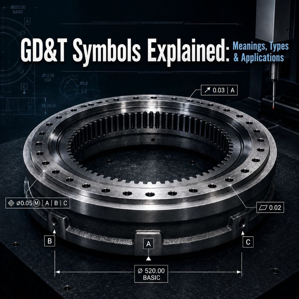
What Is GD&T?
GD&T stands for Geometric Dimensioning and Tolerancing, an internationally recognized system for defining the geometric requirements of manufactured parts. Instead of controlling only dimensions such as length or diameter, GD&T specifies how surfaces, holes, and other features should be oriented, positioned, and shaped.
The system is primarily defined by ASME Y14.5 and is increasingly adopted in global manufacturing because it provides clearer design intent and more consistent inspection criteria.
Compared with conventional dimensional tolerances, GD&T offers several advantages:
- Improves assembly consistency
- Reduces manufacturing ambiguity
- Supports functional interchangeability
- Simplifies quality inspection
- Helps optimize manufacturing costs
Why Are GD&T Symbols Important?
GD&T symbols provide a universal engineering language that connects product design, manufacturing, and inspection.
For manufacturers, they define exactly which geometric characteristics are critical and where tighter process control is required. For quality engineers, they establish objective inspection requirements using tools such as CMMs, dial indicators, and laser measurement systems.
In precision manufacturing, properly applied GD&T helps:
- Improve assembly accuracy
- Reduce dimensional variation
- Increase product reliability
- Minimize unnecessary machining costs
- Ensure consistent inspection standards
These benefits are particularly important for forged and machined components such as shafts, flanges, bearing seats, and rotating parts.
Common GD&T Symbols Explained
Below are some of the most frequently used GD&T symbols in engineering drawings.
Straightness
Straightness controls how much a line or axis can deviate from a perfectly straight condition. It is commonly applied to shafts, guide rails, and cylindrical components where smooth movement or accurate alignment is required.
Flatness
Flatness specifies how much a surface may vary from a perfectly flat plane. It is widely used on sealing surfaces, forged flanges, and mounting faces to ensure proper contact and prevent leakage or uneven loading.
Circularity (Roundness)
Circularity controls the roundness of a circular feature without referencing a datum. It is commonly used for bearing journals, precision shafts, and machined bores where rotational accuracy is critical.
Cylindricity
Cylindricity combines straightness, circularity, and taper into one tolerance requirement. It ensures the entire cylindrical surface remains within a defined tolerance zone.
Position
Position is one of the most widely used GD&T symbols. It defines the allowable location of holes, slots, pins, and other features relative to specified datums.
Accurate position tolerances help ensure proper assembly, especially in flange bolt patterns and mechanical housings.
Parallelism
Parallelism controls whether one surface or axis remains parallel to another referenced feature. It is commonly specified on guide surfaces, machined bases, and precision fixtures.
Perpendicularity
Perpendicularity ensures two features remain at a 90-degree relationship. It is widely used for mounting surfaces, shafts, and bearing seats where alignment directly affects product performance.
Runout
Runout measures the variation of a rotating surface relative to a datum axis. It is especially important for rotating shafts, ring forgings, gears, and bearing assemblies where excessive runout may lead to vibration and premature wear.
How GD&T Symbols Are Verified
Different GD&T requirements require different inspection methods.
Common measurement equipment includes:
- Coordinate Measuring Machines (CMM)
- Dial indicators
- Height gauges
- Surface plates
- Laser measurement systems
Among these, CMM inspection is the preferred solution for complex forged and machined components because it provides high accuracy, repeatability, and detailed inspection reports for features such as position, flatness, and profile.
GD&T Symbols in Forged and Machined Parts
Although GD&T principles apply to almost every manufacturing industry, they are particularly valuable in forged and machined components.
Large forgings often experience dimensional variation after forging, heat treatment, or rough machining. Applying appropriate GD&T requirements allows manufacturers to focus on critical functional features rather than unnecessarily tightening every dimension.
For example:
- Flatness helps ensure reliable sealing surfaces on forged flanges.
- Position tolerance improves bolt-hole alignment during assembly.
- Runout controls rotational accuracy for shafts and ring forgings.
- Concentricity supports stable bearing performance in rotating equipment.
By combining proper forging processes, precision CNC machining, and accurate CMM inspection, manufacturers can consistently achieve the geometric tolerances required by OEM customers.
Conclusion
GD&T symbols are much more than drawing annotations—they communicate how a part must function, assemble, and be inspected. Understanding the meaning of common symbols helps engineers, manufacturers, and quality teams reduce production errors while improving product consistency.
Whether you’re designing a new component or sourcing custom forged parts, a solid understanding of GD&T can simplify communication across the entire manufacturing process. For complex forged and machined components, combining sound GD&T practices with precision machining and reliable inspection is the key to achieving consistent quality and long-term performance.