
Forging Tolerance: Limits, Machining, and Cost
In industrial manufacturing, forging tolerance is often misunderstood. Many assume forging can achieve final dimensions like machining, but this is not the case. Forging is designed to shape material efficiently while maintaining strength, not to deliver final precision.
So, how accurate is forging, and when is machining still required? These questions are critical in OEM sourcing, where engineers and buyers must balance cost, performance, and lead time.
This article explains forging tolerance, typical accuracy ranges, and how to choose the right process to reduce cost while maintaining performance.
What Is Forging Tolerance?
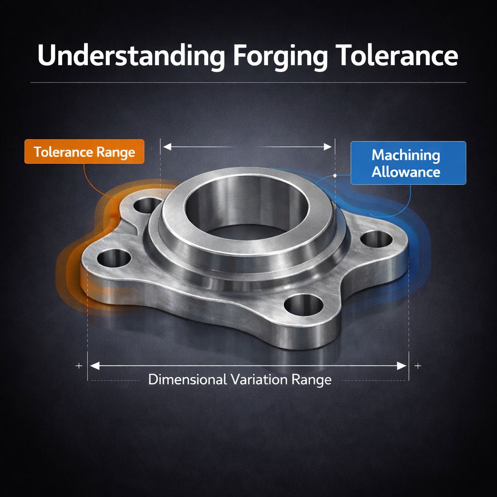
Forging tolerance is the allowable deviation between a forged part and its nominal design size. It reflects the natural limits of the forging process.
Unlike machining, which removes material with high precision, forging shapes material through deformation inside dies. This process introduces variation.
Key factors include:
- Material flow (affects deformation stability)
- Die condition (influences consistency)
- Cooling shrinkage (causes size changes)
- Process stability (affects repeatability)
Forging is less precise than machining, but it provides better strength and grain flow performance.
In practice, forging tolerance determines how much machining is required—and directly impacts overall cost.
Types of Forging Tolerances
In practical engineering, forging tolerance can be divided into several categories depending on how dimensions are controlled and evaluated:
- Dimensional tolerance: Linear size variation such as diameter, length, or thickness.
- Shape tolerance: Includes flatness, straightness, and roundness affected by material flow and cooling.
- Positional tolerance: Refers to the relative location of features such as holes or grooves.
Each type is influenced by different process factors and may require different machining strategies. Understanding these categories helps engineers define realistic tolerances and avoid unnecessary cost increases.
Forging Tolerance Range and Typical Accuracy
The forging tolerance range varies depending on the process, material, and part size. Typical ranges include:
- Hot forging: IT13–IT16
- Cold forging: IT8–IT11
- Open die forging: IT15–IT18 (depending on size)
For smaller components, tolerances can be relatively tight, but as part size increases, deviation also grows due to thermal effects and material flow complexity.
So, how accurate is forging? Compared with machining (IT6–IT7 or better), forging alone cannot meet high-precision requirements. However, it significantly reduces the amount of material that must be removed later.
In many cases, forging achieves 70–90% of the final shape, making it an efficient pre-processing step.
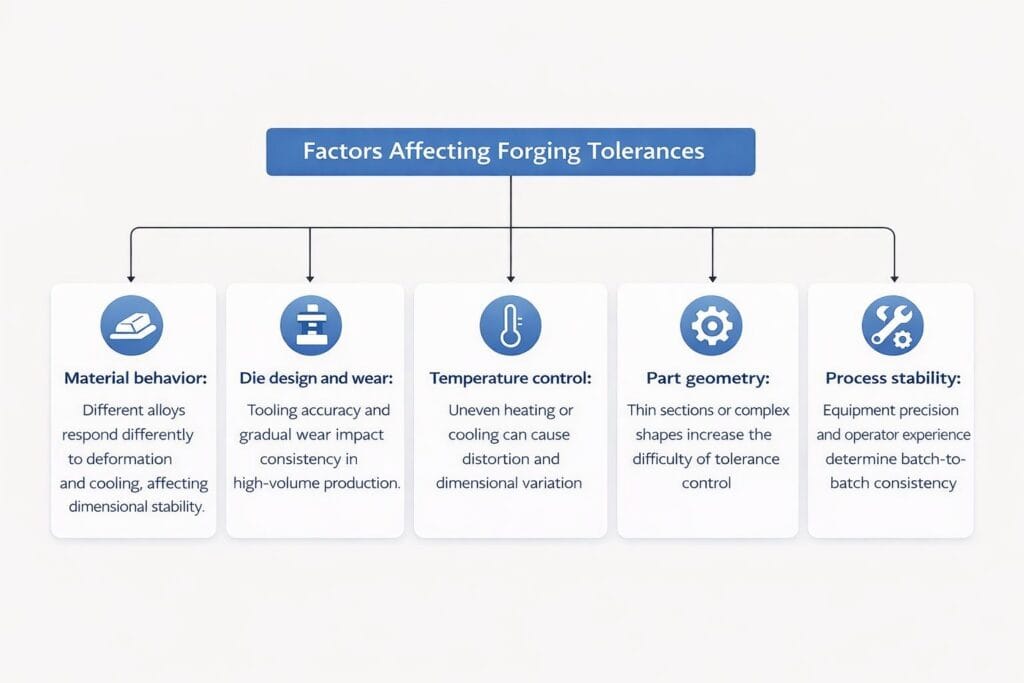
Factors Affecting Forging Tolerances
Several factors directly influence forging tolerance in real production:
- Material behavior: Different alloys respond differently to deformation and cooling, affecting dimensional stability.
- Die design and wear: Tooling accuracy and gradual wear impact consistency, especially in high-volume production.
- Temperature control: Uneven heating or cooling can cause distortion and dimensional variation.
- Part geometry: Thin sections or complex shapes increase the difficulty of tolerance control.
- Process stability: Equipment precision and operator experience determine whether consistent accuracy can be maintained across batches.
Understanding these factors helps optimize tolerance and reduce downstream machining cost.
Forging Tolerance Chart: What the Data Shows
A forging tolerance chart provides a practical reference for how dimensional variation changes with part size and process conditions. In general, tolerance increases as part size grows due to thermal effects and material flow complexity.
Typical Forging Tolerance Chart
Part Size | Typical Tolerance | Machining Allowance |
≤100 mm | ±0.5–1.5 mm | 1–2 mm |
100–500 mm | ±1.5–3 mm | 2–4 mm |
≥500 mm | ±3–6 mm | 3–6 mm |
Key observations:
- Larger forgings show greater dimensional variation
- Increased size requires more machining allowance
- Consistency depends on die quality and process control
These values are general guidelines. In real production, advanced tooling, simulation, and process control can significantly improve consistency and reduce variation.
Typical Forging Tolerance by Feature
In addition to overall size tolerance, different geometric features in forging show different levels of variation. Understanding these helps define machining allowance more accurately.
Feature | Typical Tolerance |
Flatness | 0.3–1% of length |
Straightness | 0.5–1% of length |
Hole position | ±0.8–1.5 mm |
Surface roughness | Ra 6.3–12.5 μm |
These values depend on part size, material, and process control. In critical applications, these features are typically refined by machining to ensure functional performance.
Why Forging Alone Cannot Meet Final Precision
Forging is not designed to achieve final precision. Its purpose is to create a structurally sound shape efficiently.
Several factors limit forging tolerance:
- Thermal expansion during forming
- Die wear over production cycles
- Surface roughness typically above Ra 6.3 μm
Compared to machining, where material removal is controlled precisely, forging is less predictable at micro-scale accuracy.
This is why forging vs machining tolerance is not a competition. Instead, they complement each other in manufacturing.
Machining Allowance in Forging: How It Improves Accuracy
Machining allowance in forging is a critical concept that bridges forging and machining. By leaving extra material during forging, manufacturers can:
- Compensate for dimensional variation
- Remove surface defects
- Achieve precise geometry
Typical machining allowance ranges from 1–5 mm depending on part size and tolerance requirements. Since higher allowance increases machining time and material removal, it is also one of the key drivers of forging cost.
This approach allows forged parts to achieve final tolerances such as IT6–IT8, which are required for gears, shafts, and precision assemblies.
Forging vs Casting vs Machining Tolerance
A direct comparison of forging vs casting vs machining tolerance helps clarify how each process performs in real applications:
Process | Typical Tolerance | Surface Finish | Mechanical Properties | Cost Structure | Typical Use Case |
Casting | IT14–IT18 | Rough (Ra 12.5–25 μm) | Lower, risk of porosity | Low initial cost, high defect risk | Complex shapes, low-load parts |
Forging | IT13–IT16 | Medium (Ra 6.3–12.5 μm) | Excellent (grain flow, strength) | Balanced cost-performance | Load-bearing components |
Machining | IT6–IT8 | Fine (Ra ≤1.6 μm) | Depends on material | High cost, high precision | Final finishing, precision parts |
Key insights:
- Forging provides a strong structural base but requires machining for precision.
- Casting offers shape flexibility but may compromise internal quality.
- Machining delivers accuracy but at a significantly higher material and processing cost.
In most OEM applications, the optimal solution is not choosing one process, but combining forging and machining to balance strength, accuracy, and cost.
Tolerance in Near-Net Shape Forging
Near net shape forging tolerance refers to forming parts close to final dimensions to reduce machining allowance. This approach improves material utilization and shortens machining time, especially in high-volume production.
However, it does not eliminate machining. Critical features such as bearing seats and sealing surfaces still require finishing to achieve tight tolerances. In practice, near-net forging can reduce machining allowance by 30–60%, but final accuracy still depends on secondary operations.
It should be viewed as a cost optimization strategy rather than a replacement for machining.
How to Choose the Right Forging Tolerance for Your Application
Choosing the right forging tolerance requires balancing performance, cost, and manufacturability. Tighter tolerance often increases machining time and tooling cost without adding real value.
Key factors include:
- Functional requirements (fit, load, sealing)
- Cost efficiency (material removal and machining time)
- Production volume (tooling investment justification)
- Manufacturing feasibility (geometry complexity)
In most OEM applications, the optimal solution combines forging and machining—using forging for structure and machining for precision.
The goal is not maximum accuracy, but the best balance between cost and performance.
Conclusion
Understanding forging tolerance is essential for making better manufacturing decisions. Forging provides structural strength and material efficiency, while machining ensures final precision. In most industrial applications, combining both processes offers the most practical and cost-effective solution.
If you are evaluating a new project or reviewing an existing design, a well-defined tolerance strategy can significantly improve both performance and cost control.
If helpful, feel free to share your drawings or requirements. We’re happy to offer practical feedback based on your application.