
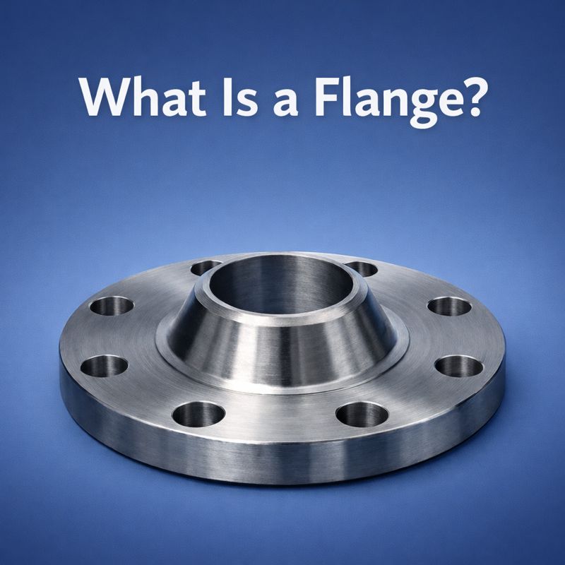
What Is a Flange?
A flange is a mechanical component used to connect, align, and secure parts in piping systems, machinery, and industrial equipment. In industrial applications, flanges provide a reliable interface that supports load transfer, sealing performance, and precise assembly. Understanding what a flange is helps engineers and procurement teams evaluate connection methods, select appropriate materials, and ensure system compatibility.
In heavy-duty and OEM equipment, flanges are often integrated into larger assemblies where dimensional accuracy, material consistency, and manufacturing coordination are important. A clear understanding of flange function and classification supports informed design decisions and efficient production planning.
Flange Meaning and Basic Function
The term flange generally refers to a protruding rim, collar, or ring designed to strengthen a joint or enable assembly between components. In industrial systems, flanges are commonly used to connect pipes, valves, pumps, and structural parts. Their basic function is to provide a secure, repeatable connection that can be assembled and disassembled when required.
Unlike permanent joints, flange connections support inspection, maintenance, and system modification without affecting surrounding components. This makes flanges a practical choice for complex industrial installations.
How Flanges Work in Mechanical and Piping Systems
Flanges work by forming a mechanical joint between two mating surfaces. Bolts provide the required clamping force, while gaskets support sealing between flange faces. This structure helps maintain alignment and load distribution under operating conditions such as pressure, temperature variation, and vibration.
Proper flange design and installation support stable system performance and predictable service behavior. For industrial equipment, this consistency is important for long-term operation planning.
Common Types of Industrial Flanges
Industrial flanges are available in multiple designs to suit different piping systems, load conditions, and maintenance requirements. Selecting the appropriate flange type helps support reliable connections, efficient installation, and long-term system performance. Below are some of the most commonly used industrial flange types and their typical characteristics.
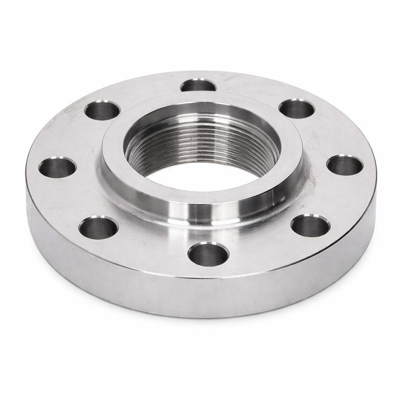
Threaded Flanges
Threaded flanges feature internal threads that connect directly to externally threaded pipes or fittings. This design supports installation without welding, making it suitable for low-pressure applications or locations where welding is impractical.
Socket-Weld Flanges
Socket-weld flanges are designed for small-diameter piping systems. The pipe is inserted into the flange socket and secured with a fillet weld, supporting smooth flow characteristics and reliable alignment in moderate service conditions.
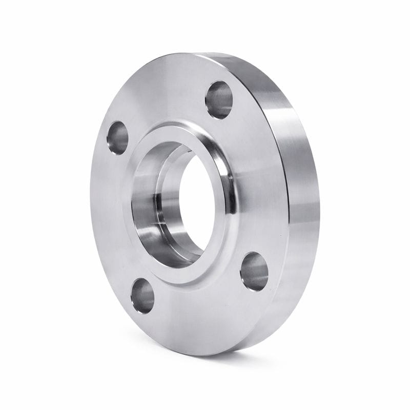
Slip-On Flanges
Slip-on flanges slide over the pipe and are welded on both sides to secure the connection. Their simple structure and broad size availability make them a common choice for general industrial piping systems.
Weld Neck Flanges
Weld neck flanges feature a long tapered hub that provides smooth stress distribution from the pipe to the flange. They are commonly used in higher-pressure, higher-temperature, or heavy-duty applications requiring enhanced structural integrity.
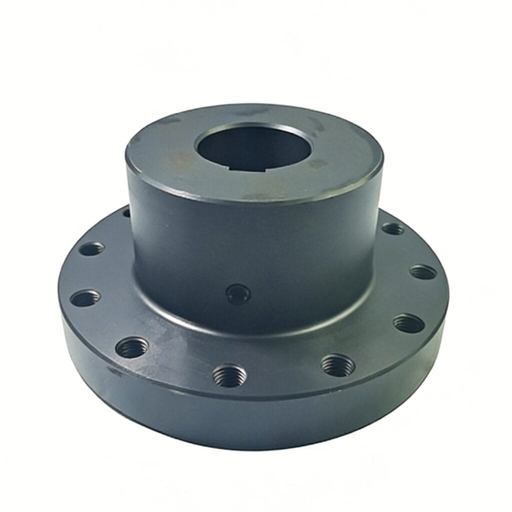
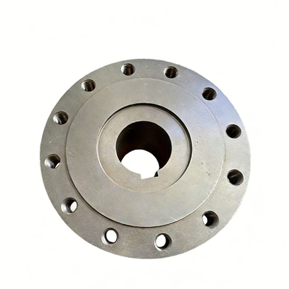
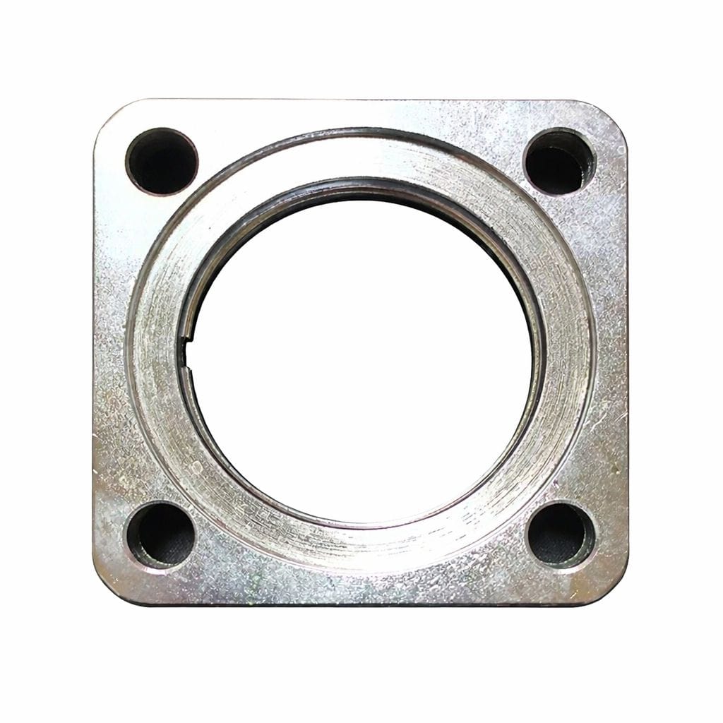
Square Flanges
Square flanges have a square outer profile instead of a circular shape. They are commonly used in structural connections, machinery frames, and equipment interfaces where alignment with flat or rectangular components is required.
This design supports stable mounting and even bolt load distribution, and square flanges are often manufactured as custom components to match specific installation and load conditions.
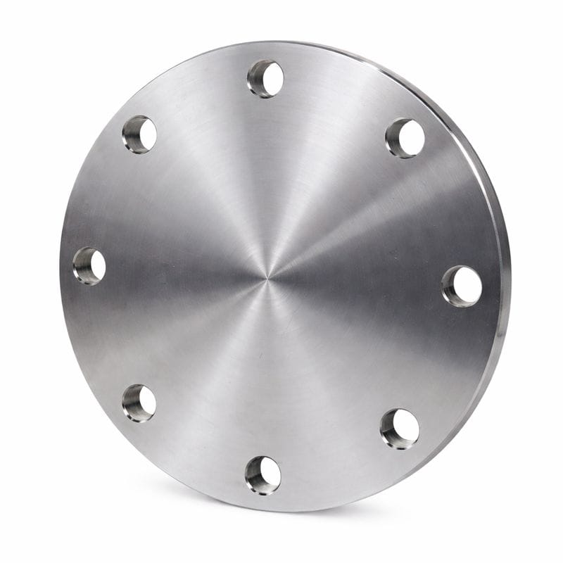
Blind Flanges
Blind flanges are solid discs used to close the end of piping systems or pressure vessels. They support system isolation and allow for future expansion, inspection, or modification.
How Are Industrial Flanges Manufactured?
Industrial flanges are manufactured through a series of coordinated processes designed to meet application requirements, dimensional accuracy, and applicable standards. The specific manufacturing route depends on material selection, flange type, and service conditions.
Typical flange manufacturing steps include:
- Material preparation
Carbon steel, alloy steel, or stainless steel is selected based on pressure rating, temperature range, and application environment. - Forming of flange blanks
Flange blanks are produced through forging, machining from plate or bar, or other forming methods depending on size and performance requirements. For heavy-duty and OEM applications, forging is commonly used to support material consistency. - CNC machining
Machining operations define critical features such as outer diameter, bolt holes, bore size, and sealing surfaces to meet drawing specifications. - Heat treatment and surface finishing (as required)
Heat treatment or surface finishing may be applied to align mechanical properties and surface condition with service requirements. - Inspection and verification
Dimensional inspection and material verification are conducted to ensure compliance with applicable standards and design documentation.
This structured manufacturing approach helps support reliable assembly, consistent performance, and compatibility across industrial systems.
Flange Sizes, Pressure Ratings, and Standards
Beyond flange type selection, flange size, pressure rating, and applicable standards play a key role in ensuring proper fit, system compatibility, and stable long-term operation. Flange dimensions must match the piping interface accurately, while pressure ratings define the allowable operating limits under specific temperature and load conditions.
Key flange size considerations include:
- Outside diameter (OD)
The overall diameter of the flange face, affecting installation clearance and mating compatibility. - Flange thickness
Related to structural strength and pressure rating requirements. - Bolt circle diameter (BCD)
The center-to-center distance between opposing bolt holes, ensuring correct alignment during assembly. - Pipe size and nominal bore
Defines internal flow diameter and connection compatibility with the piping system.
Flange classification and pressure ratings
Flanges are commonly classified based on their pressure–temperature performance range, which helps engineers select suitable components for specific operating conditions. These classifications are typically expressed using numerical pressure classes.
Common pressure classes include:
- 150#
- 300#
- 600#
- 900#
- 1500#
- 2500#
Actual allowable pressure depends on material grade, flange design, and operating temperature. As temperature increases, pressure limits are adjusted according to standard reference tables.
Applicable flange standards
Industrial flanges are produced according to internationally recognized standards to support global application consistency and sourcing coordination. Common standards include:
- ASME / ANSI– widely used in North America
- DIN / EN– commonly applied in European systems
- ISO– supporting international engineering applications
Selecting the appropriate standard helps ensure dimensional compatibility, pressure rating alignment, and consistent technical documentation across engineering and procurement workflows.
Materials Commonly Used for Flanges
Common flange materials include carbon steel, alloy steel, and stainless steel. Material selection is guided by pressure, temperature, corrosion exposure, and service environment. For industrial systems, material consistency supports predictable performance and manufacturing coordination.
How Engineers and Procurement Teams Select Flanges
Flange selection is typically guided by several coordinated technical and sourcing considerations:
- Application load and operating conditions
Engineers evaluate pressure, temperature, and mechanical loads to define performance requirements. - Material grades and applicable standards
Selection is aligned with ASTM, EN/DIN, or project-specific specifications to ensure compatibility and compliance. - Connection type and installation method
Slip-on, socket-weld, weld neck, or threaded designs are chosen based on piping layout and assembly needs. - Manufacturing method and quality control
Forging route, machining precision, and inspection capability influence consistency and reliability. - Engineering–procurement coordination
Early alignment helps match technical intent with sourcing strategy and production planning.
Conclusion
Understanding what a flange is helps clarify its role in industrial systems, from piping connections to heavy-duty equipment assembly. By considering application requirements, applicable standards, material selection, and manufacturing methods together, engineers and procurement teams can support reliable system integration and consistent long-term performance.
If you are evaluating flange design or manufacturing options for a specific project, technical discussions and early coordination can help define requirements more clearly. Inquiries are welcome, and responses are typically provided within 24 hours.