
Straight Cut Gears: How They Work in Transmission Systems
By Weforging Technical Team | Published November 4, 2026
Straight cut gears are used in industrial speed reducers, gear drives and other power transmission systems where a fixed speed ratio is required between parallel shafts.
Selecting a suitable gear pair involves more than choosing the number of teeth. Module, pressure angle, center distance and operating conditions affect gear compatibility, load capacity and transmission performance.
This article covers straight cut gear geometry, gear ratio calculations and practical design considerations, with examples from industrial power transmission applications.
Key Takeaways
- Straight cut gears are commonly used in parallel-shaft transmissions where a fixed speed ratio is required.
- Tooth count determines the gear ratio. Module and tooth count establish the reference pitch diameter, while compatible tooth geometry is essential for correct meshing.
- Straight teeth produce no helix-induced axial thrust, although noise and vibration may become more significant at higher speeds.
- Gear selection depends on torque, speed, center distance, load capacity and operating requirements—not tooth geometry alone.
What Are Straight Cut Gears?
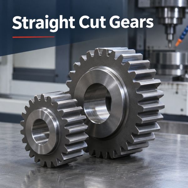
Straight cut gears, also known as spur gears, are cylindrical gears with teeth parallel to the shaft axis. They are designed to transmit rotational motion and torque between parallel shafts.
In a typical external spur gear pair, the teeth of the driving gear mesh with those of the driven gear, causing the two shafts to rotate in opposite directions. The number of teeth determines their relative speeds.
Straight cut gears are defined by their tooth orientation, not by a particular material or manufacturing method. They can be produced in different sizes, materials and configurations to meet specific transmission requirements.
How Do Straight Cut Gears Work?
Straight cut gears transmit torque through the contact force between meshing teeth. In an external gear pair, the driving gear turns the driven gear in the opposite direction. The gear ratio depends on the number of teeth on each gear.
For example, a 20-tooth driving gear operating at 1,500 rpm meshes with a 60-tooth driven gear.
Parameter | Value |
Driving gear | 20 teeth, 1,500 rpm |
Driven gear | 60 teeth, 500 rpm |
Reduction ratio | 3:1 |
Rotation direction | Opposite |
The driven gear rotates at one-third of the input speed. Ignoring transmission losses, the output torque is three times the input torque.
This is the basic principle behind speed reduction in a parallel-shaft gear drive: rotational speed decreases as torque increases.
Key Straight Cut Gear Design Parameters
Straight cut gear geometry determines the dimensions and meshing requirements of a gear pair. Module, tooth count, pressure angle, face width and backlash must be considered together when specifying gears for an industrial transmission.
Module, Tooth Count and Pitch Diameter
For a standard metric spur gear, the reference pitch diameter is calculated as:
d = m × z
Where:
- d= Reference pitch diameter (mm)
- m= Module (mm)
- z= Number of teeth
For a standard external spur gear pair without profile shift, the standard center distance is:
a = m × (z₁ + z₂) / 2
Using the same 20-tooth and 60-tooth gear pair, with a module of 3 mm:
Gear Parameter | Driving Gear | Driven Gear |
Module | 3 mm | 3 mm |
Number of teeth | 20 | 60 |
Reference pitch diameter | 60 mm | 180 mm |
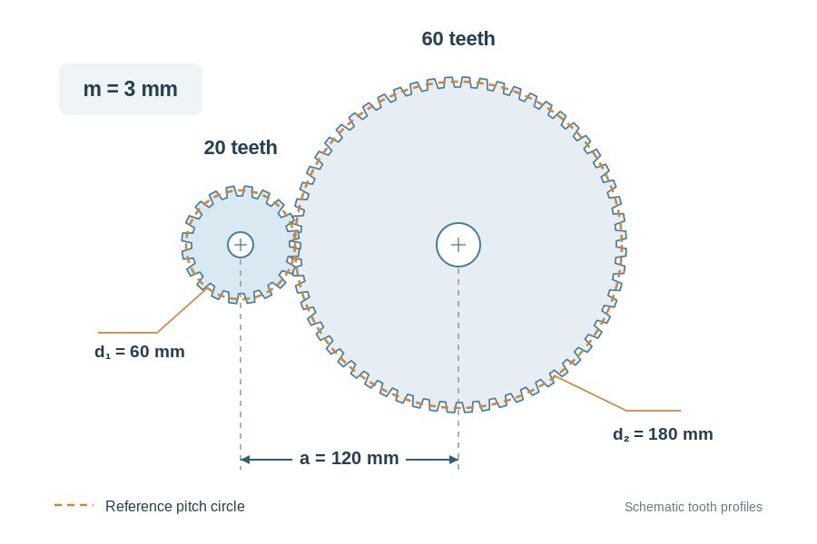
Illustration based on standard external spur gear geometry without profile shift. Tooth profiles are schematic.
The standard center distance is 120 mm.
This relationship applies to the stated standard gear geometry. Profile shift and other design requirements may affect the specified operating center distance.
Mating spur gears must have compatible modules, pressure angles and tooth profiles. Tooth count determines the ratio, but it does not establish whether two gears can mesh correctly.
Pressure Angle, Face Width and Backlash
The pressure angle determines the direction of the tooth contact force in a spur gear pair. A 20° pressure angle is common in standard involute gears, and mating gears must have compatible pressure angles and tooth profiles for correct engagement.
Face width is the axial width of the gear teeth. A wider face can provide greater load-carrying capacity when the gear pair is properly designed, but it also requires more installation space along the shaft.
Backlash is the clearance between the non-contacting flanks of mating gear teeth at the specified operating center distance. It accommodates lubrication, manufacturing tolerances and thermal expansion. Too little backlash can cause binding, while excessive backlash may affect positioning accuracy and increase impact during load reversal.
For a custom straight cut gear pair, these parameters should be specified alongside module, tooth count and center distance rather than treated as separate dimensions.
Straight Cut Gears vs Helical Gears
Straight cut gears and helical gears both transmit torque between parallel shafts, but their tooth orientation affects how the gears engage and the loads they generate.
Design Factor | Straight Cut Gears | Helical Gears |
Tooth direction | Parallel to shaft axis | Inclined to shaft axis |
Tooth engagement | Less gradual | More gradual |
Helix-induced axial thrust | None | Present |
Noise | Typically more noticeable | Typically quieter |
For industrial transmissions, the choice depends largely on operating speed, noise requirements and how the shaft and bearing arrangement accommodates gear loads. Straight cut gears avoid helix-induced axial thrust, while helical gears generally provide smoother engagement.
Neither design is automatically stronger or more efficient. The result depends on the gear geometry, load and operating conditions.
For further information on helical tooth geometry and manufacturing, see Weforging’s Helical Gears guide.
Where Are Straight Cut Gears Used?
Straight cut gears are used in industrial gear drives, speed reducers and mechanical transmission systems where parallel-shaft gearing meets the required load, speed and noise limits. Their application depends on the transmission layout and the function of each gear stage.
Industrial Speed Reducers and Gear Drives
Straight cut gears can form the reduction stage in a parallel-shaft gearbox or a dedicated gear drive. Their straight tooth geometry avoids helix-induced axial thrust, which can be useful in certain shaft and bearing arrangements.
For these applications, gear selection depends on transmitted torque, operating speed, available space and acceptable noise levels. The gear pair must be sized for the intended duty rather than selected on tooth geometry alone.
Weforging manufactures custom transmission components, including gears and shafts, with forging and CNC machining processes selected according to OEM drawings and production requirements.
Machine Tools and Auxiliary Drives
Straight cut gears are used in conventional machine-tool speed-change gear trains and selected mechanical feed or auxiliary drives. They provide defined speed ratios between shafts and can be arranged as individual gear pairs or part of a larger gear train.
In these mechanisms, tooth count and available installation space influence the gear arrangement. Operating speed, load and duty cycle determine whether a straight cut gear is suitable.
Multi-Stage Power Transmission
In a multi-stage transmission, straight cut gear pairs can be arranged across input, intermediate and output shafts. Each stage transfers torque to the next, allowing a greater overall speed reduction than a single gear pair.
Compound gear components can be manufactured as a one-piece design from a forged blank or as a multi-piece assembly with separately machined gears. The choice depends on the gear geometry, load requirements, machining access and assembly needs.
Compound straight cut gear components. Depending on the design, gears can be machined from a one-piece forged blank or produced separately for assembly.
A one-piece design eliminates the joints between integrated gear features, while a multi-piece arrangement allows individual gears to be manufactured and assembled separately. Both approaches require control of gear positioning and dimensional accuracy.
Weforging supplies custom gears and shafts for industrial transmissions, with forging and CNC machining processes selected to suit OEM drawings and production requirements.
When Should Straight Cut Gears Be Used?
Straight cut gears are well suited to parallel-shaft transmissions where their load capacity, operating speed and noise characteristics meet the design requirements.
Their relatively simple tooth geometry and established manufacturing methods can be advantageous for industrial gear production. However, higher operating speeds may make meshing noise more noticeable, particularly where acoustic limits are strict.
Before selecting a straight cut gear pair, engineers should check the required torque, gear dimensions, available installation space and duty cycle. Material selection and tooth geometry must also support the intended load.
Straight cut gears remain a practical choice when these conditions are satisfied, but tooth simplicity alone should not determine the design.
How Are Straight Cut Gears Made?
Straight cut gears are manufactured through blank preparation, machining, tooth cutting, heat treatment and inspection. The process sequence is determined by the material, gear geometry and accuracy requirements.
Forged Blanks and Material Selection
For heavily loaded industrial gears, forged steel blanks are often considered where the required material properties and production volume justify forging. Smaller gears or low-volume parts may be machined from bar stock.
Forging dimensions must leave sufficient stock for turning, tooth cutting and any subsequent finishing. The material and forging condition also need to be compatible with the specified heat treatment.
CNC Machining and Tooth Cutting
CNC turning establishes the bore, mounting faces and other reference surfaces before gear cutting. These datums help maintain the required relationship between the gear teeth and the mounting features.
Gear teeth are then produced by hobbing or shaping, depending on the gear geometry and tool access. Accurate workholding and alignment are essential to control tooth position and runout relative to the bore.
The video shows a gear tooth-cutting operation during the machining of a custom gear component.
Heat Treatment and Inspection
Heat treatment is selected to meet the required hardness and mechanical properties. Where distortion affects the specified tolerances, additional finishing may be needed after heat treatment.
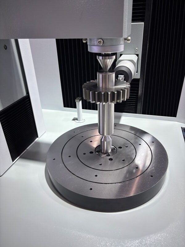
Gear inspection follows the drawing requirements. Tooth profile and lead are checked using dedicated gear measuring equipment, while pitch and runout are verified using the appropriate measurement procedures. CMM inspection can also be used for bores, faces and related geometric tolerances.
Weforging supplies custom spur gears from forged blanks through CNC machining and finished components, based on OEM drawings and the agreed production scope.
Choosing Straight Cut Gears for Industrial Transmissions
Straight cut gears remain a practical solution for many parallel-shaft transmission systems. Their simple tooth arrangement is useful, but the correct gear design begins with tooth count, module, pressure angle, center distance and operating requirements.
For industrial applications, these parameters should be evaluated alongside speed, torque, noise limits and manufacturing accuracy. A well-matched gear pair is more important than selecting a tooth type based on general advantages alone.