
Helical Gears: Types, Applications & Manufacturing
By Weforging Technical Team | Published October 23, 2026
Helical gears are used in industrial transmissions where smooth tooth engagement and reliable torque transfer matter. Their angled teeth reduce abrupt contact, but also introduce axial thrust and more demanding manufacturing requirements.
For custom steel helical gears, tooth design is only part of the engineering decision. The choice between cast, bar-machined and forged blanks affects material utilization, mechanical properties and the machining route. This guide examines those choices, including CNC feasibility, heat treatment and the inspection needed to verify finished gears.
Key Takeaways
- Gear design: Helix angle, tooth geometry and axial thrust affect both transmission performance and manufacturing requirements.
- Blank selection: forging, bar-stock machining andCasting serve different needs. Forged blanks are worth considering for suitable heavy-duty steel gears.
- Mechanical properties: Yield strength, tensile strength, toughness and heat treatment must be evaluated alongside gear fatigue requirements.
- Manufacturing feasibility: Tool access, machining datums and finishing allowances should be reviewed before production.
- Inspection: Material testing, dimensional checks and dedicated tooth measurements verify different aspects of the finished gear.
What Are Helical Gears?
Helical gears are cylindrical gears with teeth inclined at an angle to the shaft axis. As the gears rotate, contact progresses across the tooth face instead of beginning across the full width simultaneously.
This overlapping engagement generally produces smoother operation than comparable spur gears. The trade-off is axial thrust, which must be supported by the shaft and bearing arrangement. Gear accuracy, lubrication and alignment remain important regardless of the selected helix angle.
Types of Helical Gears
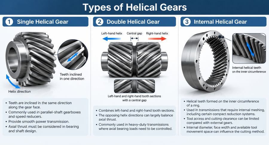
Helical gear configurations differ not only in tooth arrangement but also in how they can be manufactured. Tool access, axial thrust and available finishing methods should be considered during selection.
Single Helical Gears
Single helical gears have teeth inclined in one direction. They are widely used in parallel-shaft gearboxes, with axial thrust supported by the bearing arrangement. Their external teeth can often be produced by conventional gear hobbing, subject to part geometry and machine capability.
Double Helical and Herringbone Gears
Double helical gears combine opposing left-hand and right-hand tooth sections to largely balance axial thrust under suitable loading conditions. A central gap commonly provides cutting-tool clearance. Herringbone gears have continuous V-shaped teeth without that gap, which can require a different manufacturing method.
Internal Helical Gears
Internal helical gears have angled teeth inside a ring. The inner diameter, face width and adjacent shoulders can restrict cutting-tool movement. Before selecting shaping, power skiving or another process, the manufacturer must confirm tool clearance and machine capability.
Advantages and Limitations of Helical Gears
Helical gears generally provide smoother load transfer and lower operating noise than comparable spur gears, particularly at higher speeds. Their overlapping tooth contact also helps distribute loads during transmission.
However, these advantages involve engineering trade-offs. Single helical gears generate axial thrust, which must be supported by the bearing arrangement. Tooth accuracy, lubrication and alignment also affect performance. In addition, helical tooth geometry can make manufacturing and inspection more demanding.
Engineering Factor | Advantage | Limitation |
Tooth engagement | Gradual engagement reduces load fluctuations | Performance depends on tooth accuracy and alignment |
Load transmission | Greater tooth contact overlap | Load capacity still depends on geometry and load distribution |
Operating noise | Generally quieter at higher speeds | Poor finishing or alignment can increase noise |
Axial force | — | Requires suitable bearings and shaft support |
Manufacturing and inspection | Suitable for smooth-running precision drives | Helical tooth geometry can require more complex cutting and inspection |
Key Helical Gear Design Parameters
A helical gear cannot be evaluated by diameter and tooth count alone. Several geometric parameters influence tooth contact, load distribution, bearing forces and manufacturing requirements.
Helix Angle, Module and Pressure Angle
The helix angle affects tooth contact overlap and axial thrust. A larger helix angle can improve engagement smoothness, but it also increases axial force for a given tangential load.
For a single helical gear, the axial force magnitude can be estimated as:
Fa = Ft × tan β
Where Fa is axial force, Ft is tangential force and β is the helix angle.
For example, a tangential force of 2,000 N at a 20° helix angle produces approximately 728 N of axial force. The bearing arrangement must accommodate this load.
Normal module and transverse module must also be distinguished when specifying tooth geometry:
mt = mn / cos β
Where mt is transverse module and mn is normal module.
Pressure angle and mating gear geometry must also be compatible. Mixing normal and transverse parameters can result in incorrect tooth specifications.
Face Width, Backlash and Gear Accuracy
Face width influences the available tooth contact area. However, increasing face width does not automatically improve load distribution. Shaft deflection, alignment and lead modifications become important, particularly for wider gears.
Backlash should be specified according to the transmission design and operating conditions. Tooth profile, lead and pitch accuracy also affect vibration, contact patterns and service life.
For custom helical gears, bore tolerances, reference datums and machining allowances should be reviewed before selecting the blank and machining sequence.
Cast vs Machined vs Forged Helical Gears
A helical gear can be produced from a casting, rolled bar stock or a forged blank. The choice depends on gear size, loading, material requirements, production volume and the amount of machining required. No single route is suitable for every gear design.
Manufacturing Route Comparison
Factor | Casting | Bar-stock machining | Forging |
Typical consideration | Large or complex blanks | Prototypes and smaller batches | Suitable loaded steel gears |
Material utilization | Can approach complex shapes | High removal on bulky parts | Preforms can reduce removal |
Main process risk | Casting defects and variation | Excessive stock removal | Forging control and allowances |
Mechanical properties | Grade, quality and heat treatment | Stock condition and heat treatment | Forging history and heat treatment |
Tooth cutting | Usually required | Required | Usually required |
For OEM production, forged gear blanks should be evaluated against the actual gear drawing rather than selected solely because the application is described as heavy-duty.
Materials and Heat Treatment for Helical Gears
Material selection depends on transmitted torque, operating speed, shock loading and expected service life. Industrial steel gears may require different combinations of core strength, surface hardness and toughness. These requirements also influence the choice of starting material and manufacturing route.
Common Gear Materials
Medium-carbon and alloy steels are commonly used for industrial helical gears. AISI 4140 is often selected for quenched-and-tempered components, while AISI 8620 is commonly used for carburized gears. In both cases, the specified heat treatment is essential to achieving the required mechanical properties.
For larger or heavily loaded steel gears, custom forging may be suitable when component geometry, material requirements and production volume support the use of a forged blank. However, forging alone does not guarantee better gear performance. Material quality, heat treatment and subsequent machining all affect the finished component.
Why Do Yield and Tensile Strength Matter?
Yield strength indicates the stress at which a material begins to deform plastically. Tensile strength is the maximum engineering stress reached during a tensile test. Both may be specified for steel gear blanks and other load-bearing components.
However, a high tensile-strength result does not prove that the gear will resist tooth-root fatigue or surface pitting. Those failure modes depend on tooth geometry, loading, material condition, surface treatment and other factors.
When yield and tensile strength are specified, the drawing or purchase requirements should establish the material condition, test method, specimen location and acceptance criteria. For forged blanks, these requirements should be agreed upon before production.
How Does Heat Treatment Affect Gear Manufacturing?
Heat treatment determines whether a steel gear blank can achieve the required combination of strength, toughness and hardness. Quenching and tempering are commonly used for through-hardened components, while carburizing and subsequent hardening produce a wear-resistant surface with a comparatively tougher core.
For forged gear blanks, the heat-treatment route should be selected according to the steel grade, section size and specified mechanical properties. Hardness testing and, where required, tensile testing can verify whether the material meets the agreed acceptance criteria.
How Are Helical Gears Manufactured?
Helical gear manufacturing begins with selecting a suitable blank and planning the machining sequence. The process depends on gear geometry, material, heat treatment and accuracy requirements. For custom industrial gears, machining datums and finishing allowances should be considered before tooth cutting begins.
Forged and Other Gear Blanks
Forged gear blanks are used for certain industrial gears when component size, loading requirements and production conditions justify forging. Depending on the geometry, a forged blank may be supplied as a solid disc, ring or near-net-shape component.
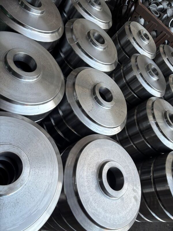
Forging produces the starting shape rather than the finished helical teeth. The blank still requires machining allowances for the bore, faces and tooth-cutting operations. Blank selection also affects material utilization and machining costs.
The internal gear blanks shown here have undergone forging, normalizing and rough machining. They are awaiting final machining, internal gear cutting and spline broaching. This intermediate stage illustrates why machining allowances and process sequencing must be considered before the teeth are produced.
CNC Turning and Gear Cutting
CNC machining establishes the bore, faces and reference surfaces before gear cutting. Depending on the gear configuration, helical teeth may be produced by hobbing, shaping, power skiving or other suitable methods.
For forged gear blanks, consistent machining datums are important throughout production. During secondary setups, operators may indicate previously machined reference surfaces to check alignment before machining continues.
This helps reduce setup-related errors that can affect bore-to-tooth concentricity and radial runout. These relationships should be controlled before final finishing.
Final Finishing and Gear Inspection
After heat treatment, grinding or other finishing operations may be required to achieve the specified bore dimensions, runout and tooth accuracy. The machining plan must account for possible distortion and retain sufficient finishing allowance on critical surfaces.
Final inspection should verify the geometric relationships established during machining. A coordinate measuring machine (CMM) or other suitable equipment can check bore dimensions, reference surfaces and specified runout requirements.
Tooth profile, lead and pitch deviations require appropriate gear measurement capabilities, often provided by dedicated gear inspection equipment. These results should be evaluated against the applicable drawing tolerances and gear accuracy standard.
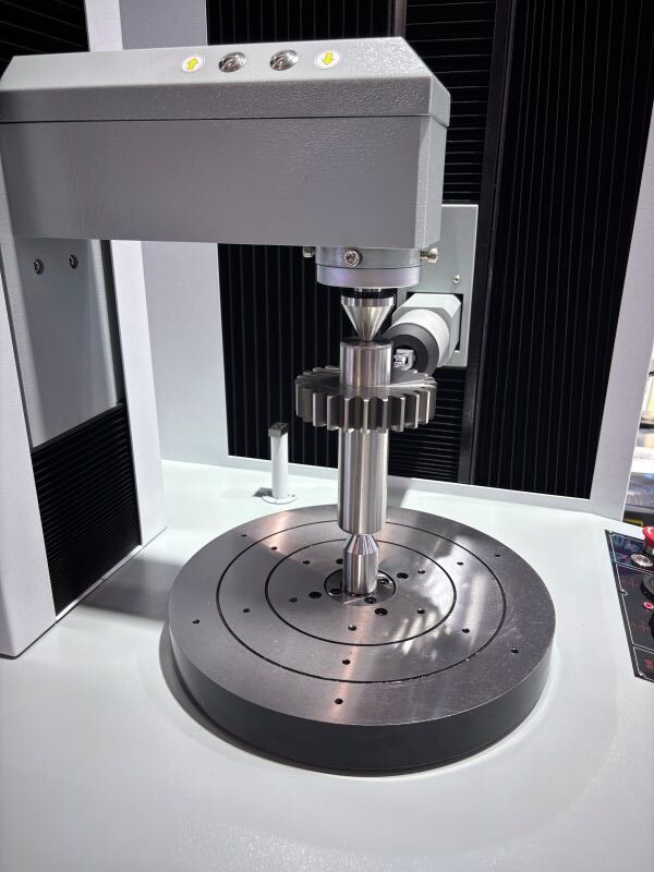
The image above shows a spur gear shaft set up for tooth profile and lead inspection. Although the component has straight teeth, similar measurement principles apply to helical gears, with inspection procedures adapted to the specified tooth geometry.
Common Applications of Helical Gears
Helical gears are widely used in industrial gearboxes, speed reducers, machine tools and heavy-duty transmission systems. Their gradual tooth engagement makes them suitable for applications requiring smooth torque transfer and controlled operating noise.
Industrial Gearboxes and Power Transmission
Helical gears are commonly used in parallel-shaft reduction stages alongside other industrial gearbox components. Their selection depends on transmitted torque, operating speed and the arrangement of the shafts and bearings.
In heavy-duty gearboxes, axial thrust, housing stiffness and lubrication must also be considered. These factors affect load distribution and long-term transmission performance, particularly under continuous or variable loading.
Heavy Machinery and Precision Equipment
Helical gears are used in heavy machinery, machine tools and industrial drive systems, but the operating requirements differ.
Heavy machinery may expose gears to shock loads and fluctuating torque, making material selection and fatigue resistance important. In machine tools, tooth accuracy, vibration and transmission smoothness often receive greater attention.
For OEM equipment, gear geometry and manufacturing tolerances should be evaluated together with shaft alignment, bearing arrangements and the surrounding housing.
What Should OEM Buyers Specify for Custom Helical Gears?
Custom helical gear drawings need more than outside diameter and tooth count. Missing tooth geometry, material specifications or inspection requirements can lead to manufacturing errors and delays. The following details should be confirmed before production.
- Gear geometry:Normal module, tooth count, helix angle and hand, normal pressure angle, face width and profile shift where applicable.
- Material and heat treatment:Steel grade, required hardness, effective case depth where applicable, and specified mechanical properties.
- Gear accuracy:Applicable ISO or AGMA accuracy standard, critical tooth deviations and backlash requirements for the mating gear arrangement.
- Machining features:Bore, keyway, shaft interface, reference datums, geometric tolerances and bore-to-tooth runout.
- Blank and production scope:Forged or bar-stock blanks selected according to geometry, loading and production volume, with the required machining stage defined.
- Inspection and delivery:Agreed inspection records, material traceability, heat treatment documentation and delivery as a blank, rough-machined part or finished component.
For mating gears, the center distance and matching tooth geometry should also be confirmed. In OEM projects involving custom gears and shafts, Weforging reviews customer drawings to establish suitable forging, machining and inspection requirements within the agreed production scope.
Conclusion: Helical Gear Design and Manufacturing
A helical gear’s performance depends on more than its tooth geometry. Material condition, loading, heat treatment and manufacturing accuracy all influence how the gear behaves in service.
For custom steel gears, the starting blank deserves attention. Casting, bar-stock machining and forging each have suitable applications, while forged blanks may offer particular advantages when material requirements, loading and component geometry justify the process.
The manufacturing route should then be checked for tool access, datum control, finishing allowances and inspection capability. Weforging supports OEM gear and shaft projects to customer drawings, with the agreed production scope covering forged blanks, rough-machined parts or finished components.