
Why Forging Ratio Matters in OEM Forged Parts
In simple terms, forging ratio refers to how much a material is deformed during the forging process. It is a key factor that determines internal structure, grain flow, and mechanical performance in forged components.
In OEM manufacturing, decisions are often driven by price and lead time. However, experienced engineers know that internal quality is established much earlier — at the forging stage. In many cases, an insufficient forging ratio is a hidden cause of premature failure in load-bearing parts such as shafts and gear rings.
This article explains forging ratio from an engineering perspective, including how it is calculated, how it affects performance, and how it should be evaluated in real OEM sourcing decisions.
What Is Forging Ratio in Steel Forging
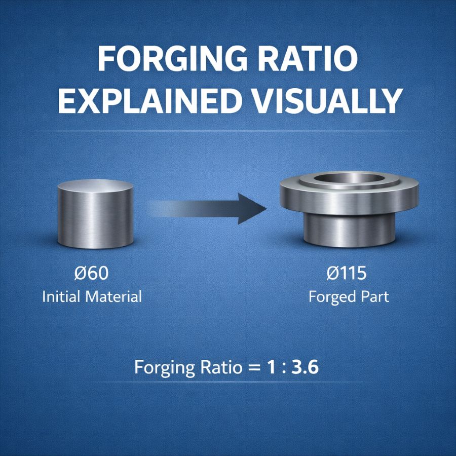
The forging ratio describes the degree of plastic deformation applied to a material during forging. It is commonly expressed as the ratio between the initial and final cross-sectional areas.
However, in engineering practice, forging ratio is not just a mathematical value. It represents how effectively the internal structure has been transformed. A proper forging ratio leads to:
- Closure of internal porosity and voids
- Refinement of grain structure
- Alignment of grain flow along load paths
It is closely related to the forging reduction ratio, and in many cases, both terms are used interchangeably.
More importantly, forging ratio should always be evaluated in combination with deformation path and process design, not as an isolated parameter.
How to Calculate Forging Ratio (With Practical Example)
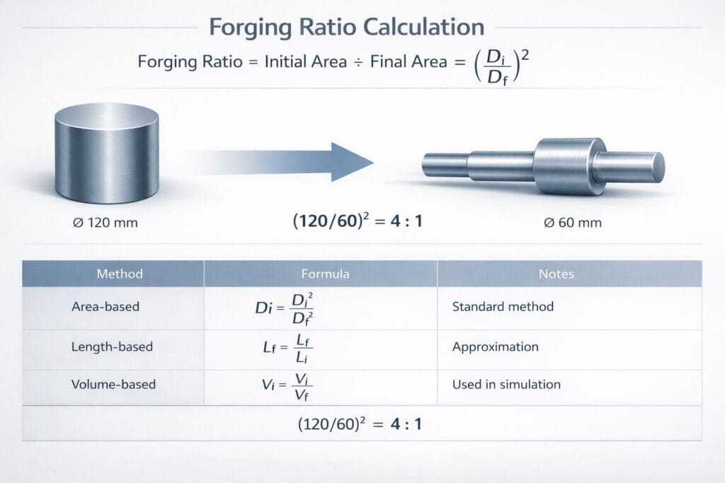
The most common calculation method is based on cross-sectional area:
Forging Ratio = Initial Area ÷ Final Area
Example:
A steel bar with a diameter of 120 mm is forged into a shaft of 60 mm:
(120²) ÷ (60²) = 4:1
In real engineering applications, different calculation approaches may be used depending on geometry:
Method | Application | Notes |
Area-based | Shafts, bars | Most common |
Length-based | Elongated parts | Useful for open die forging |
Volume consistency | Complex shapes | Used in process simulation |
Key insight:
The goal is not precision calculation, but understanding deformation intensity and its effect on structure.
Why Forging Ratio Matters: Impact on Mechanical Properties
Forging ratio is one of the most critical factors influencing mechanical performance.
- Grain Flow Optimization
Higher forging ratios promote continuous and directional grain flow, improving load-bearing capacity.
- Fatigue Resistance
Aligned grain structure significantly enhances resistance to cyclic loading, which is essential for shafts and rotating components.
- Defect Elimination
Adequate deformation helps eliminate internal defects such as voids and segregation.
Engineering Balance
- Too low → incomplete densification
- Too high → excessive deformation, potential damage
The optimal forging ratio is always application-specific.
Recommended Forging Ratio for Different Components
In practical applications, the required forging ratio varies depending on the component type and loading conditions. Typical guidelines include:
- Shafts: Higher forging ratios are recommended to improve fatigue resistance and ensure continuous grain flow along the axis.
- Gear rings: Moderate to high ratios help achieve uniform circumferential grain structure.
- Large structural parts: The ratio must balance deformation and process limitations.
In OEM projects, the optimal forging ratio is determined not only by calculation, but also by material grade, geometry, and manufacturing process.
Minimum Forging Ratio Requirements and Industry Standards
Typical forging ratio requirements vary by application:
Application | Typical Ratio |
General parts | ≥ 3:1 |
Load-bearing parts | 4:1–6:1 |
High-reliability components | ≥ 6:1 |
Industry-specific considerations:
- Energy equipment → higher safety margins
- Mining machinery → fatigue resistance focus
- Heavy equipment → impact + durability
Standards such as ASTM and EN often specify minimum deformation levels indirectly through mechanical requirements.
Forging Ratio in Different Forging Processes
The achievable forging ratio varies significantly depending on the forging process, as each method offers different deformation mechanisms and structural outcomes.
Open Die Forging (Shaft Forging)
Open die forging allows large plastic deformation, making it suitable for achieving higher forging ratios in shafts and heavy components. It promotes axial grain flow but may result in less uniform deformation compared to controlled processes.
Ring Rolling Forging
Ring rolling is highly effective for ring-shaped components. It produces seamless structures with continuous circumferential grain flow, ensuring uniform deformation and optimal forging ratio distribution. This makes it ideal for high-performance applications such as gear rings.
In this process, deformation continues during rolling. While forging ratio reflects the initial deformation, rolling ratio describes the deformation during ring expansion. In practice, both influence grain flow and structure, but forging ratio remains the primary parameter.
Closed Die Forging
Closed die forging offers high dimensional accuracy, but deformation is constrained by die geometry. As a result, the achievable forging ratio is more limited and must be carefully engineered during preform design.
In practice, selecting the right process is not only about shape, but about achieving the required forging ratio and grain flow for performance.
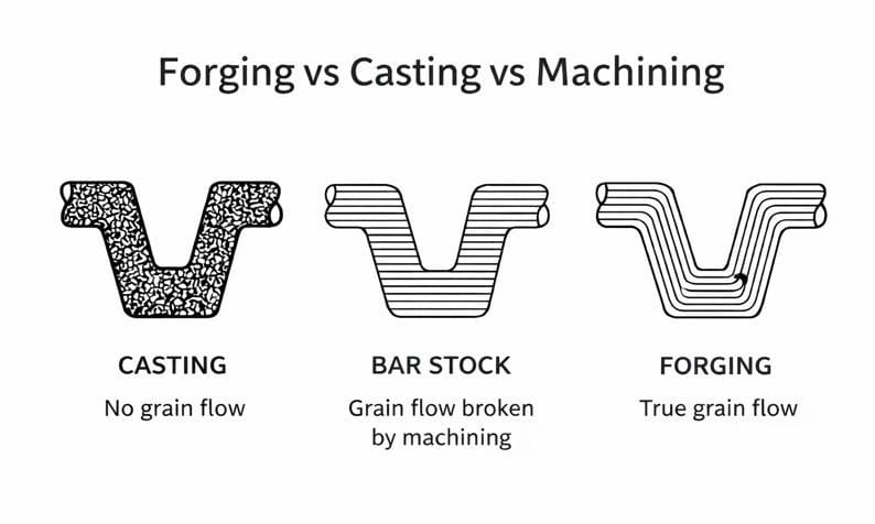
Forging vs Casting vs Machining: Why Forging Ratio Matters
Method | Internal Structure | Defect Control | Performance |
Casting | Random grain | Limited | Lower |
Machining | No improvement | Depends on material | Neutral |
Forging | Directional grain flow | Strong (via deformation) | Superior |
Although these processes can produce similar shapes, their internal structures differ significantly. The key factor is the forging ratio, which reflects controlled plastic deformation.
A sufficient forging ratio aligns grain flow and closes internal voids, improving fatigue resistance. Without it, forged parts may perform similarly to cast components.
For a deeper comparison, see our guide on forging vs casting, and how grain flow in forging improves performance.
How Forging Ratio Is Verified in Quality Control
Forging ratio cannot be measured directly in finished parts, but is verified through its impact on internal structure and performance.
Key verification methods include:
- Ultrasonic Testing (UT): detects internal defects such as voids
- Macrostructure examination: evaluates deformation uniformity
- Grain flow inspection: confirms directional fiber alignment
In practice, these results indicate whether sufficient deformation has been achieved, ensuring the forging ratio meets engineering requirements.
Common Misunderstandings About Forging Ratio
In practice, many misunderstandings about forging ratio can lead to incorrect engineering or sourcing decisions.
Common misconceptions include:
- “A higher forging ratio always means better performance”
Excessive deformation may damage material structure or increase cost without real performance gain. - “All components require the same forging ratio”
Different applications (shafts, rings, structural parts) require different deformation strategies. - “Forging ratio alone determines quality”
Material selection, heat treatment, and machining are equally critical.
Engineering insight:
Forging ratio should be evaluated as part of a complete manufacturing system, not as an isolated parameter.
How to Choose the Right Forging Ratio for OEM Parts
Selecting the right forging ratio for OEM parts requires balancing performance, manufacturability, and cost.
Key factors include:
- Load conditions
Fatigue-loaded parts require higher forging ratios to ensure grain flow continuity. - Material type
Alloy steels often require stricter deformation control than carbon steels. - Component geometry
Shafts benefit from axial grain flow, while rings require circumferential grain continuity. - Manufacturing process
Open die forging, ring rolling, and closed die forging offer different deformation capabilities.
Practical insight:
The optimal forging ratio is not the maximum value, but the one that ensures reliable performance under real operating conditions.
Conclusion
Forging ratio is a key factor that determines internal structure, grain flow, and long-term performance of forged components.
For OEM applications, it is not just about reaching a specific ratio, but about controlling the entire process — from forging to machining and inspection — to ensure consistent quality.
If you are evaluating forged parts, feel free to share your drawings or requirements. We typically respond within 24 hours to discuss practical solutions from an engineering perspective.