
What Is a Pinion Gear? Types, Uses & Manufacturing
A pinion gear is the smaller gear in a gear pair and is commonly used to transfer motion, torque and speed in mechanical transmission systems. Unlike a specific gear type, “pinion” describes the role of a gear within a system, which can be designed as spur, helical, bevel or other configurations.
Because pinion gears usually operate at higher speeds and experience frequent tooth contact, factors such as material selection, tooth accuracy and heat treatment have a direct impact on service life and reliability.
This guide explains how pinion gears work, common types, materials, manufacturing processes and key considerations for selecting custom forged pinion gears for industrial applications.
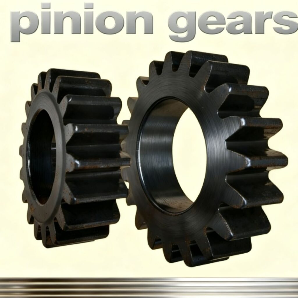
What Is a Pinion Gear?
A pinion gear is the smaller member of a gear set that meshes with a larger gear, ring gear, or rack. Depending on the application, it can act as either the driving gear or the driven gear.
Its primary functions include:
- Transmitting torque
- Changing rotational speed
- Modifying output force
- Controlling motion direction
The term “pinion” refers to its relative size within the gear pair rather than a specific gear design.
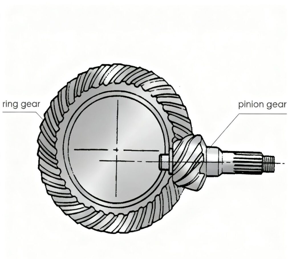
How Does a Pinion Gear Work?
When two gears mesh together, the teeth transfer motion and force from one gear to another. In most gear systems, the pinion gear is the smaller member of the gear pair and typically rotates at a higher speed than the mating gear.
The relationship between the number of teeth on the pinion and the mating gear determines the gear ratio, which affects output speed and torque. This principle is widely used in industrial gearboxes, mining equipment, construction machinery, and other power transmission systems.
Gear Ratio Formula
Gear Ratio = Number of Teeth on Driven Gear ÷ Number of Teeth on Pinion
For example:
- Pinion Gear = 20 teeth
- Mating Gear = 80 teeth
Gear Ratio = 80 ÷ 20 = 4:1
This means the larger gear rotates once for every four revolutions of the pinion gear. As rotational speed decreases, output torque increases.
Pinion Gear vs Gear: What's the Difference?
The terms “gear” and “pinion gear” are often used together, but they describe different roles within a gear system.
| Feature | Pinion Gear | Mating Gear |
|---|---|---|
| Size | Smaller gear | Larger gear |
| Rotational Speed | Higher | Lower |
| Torque Output | Lower | Higher |
| Tooth Contact Frequency | More frequent | Less frequent |
| Wear Risk | Higher | Lower |
| Manufacturing Requirement | Usually requires higher precision | Depends on application |
Because a pinion gear operates at higher speeds and experiences more tooth engagement cycles, it often requires better material properties, accurate tooth profiles and improved surface treatments.
For heavy-duty applications, factors such as fatigue resistance, hardness consistency and dimensional accuracy directly influence performance.
Common Types of Pinion Gears
Spur Pinion Gear
A spur pinion gear features straight and parallel teeth. It is simple, efficient, and cost-effective, making it ideal for general-purpose machinery, elevators, packaging equipment, and light-duty reducers. This design represents the traditional spur and pinion gear setup.
Helical Pinion Gear
Helical pinions feature angled teeth that allow multiple teeth to engage at once, providing smoother and quieter operation. They are commonly used in automotive transmissions, industrial gearboxes, and heavy-duty machinery.
Bevel and Spiral Bevel Pinion
These pinions allow torque transmission at right angles and are essential components in differential systems and angular gear drives. Spiral bevel pinions offer improved tooth strength and smoother contact.
Internal Pinion
Used in planetary gear sets and compact hydraulic drives, internal pinions mesh with gears containing inward-facing teeth.
What Materials Are Used for Pinion Gears?
The performance of a pinion gear depends heavily on material selection.
Common materials include:
| Material | Typical Application |
|---|---|
| 20CrMnTi | Carburized gears |
| 42CrMo | Heavy-duty industrial gears |
| SCM440 | High-strength gear systems |
| 4140 Steel | General industrial applications |
| 8620 Steel | Gearbox components |
These materials provide a balance of strength, toughness, wear resistance, and heat-treatment compatibility.
Depending on application requirements, pinion gears may undergo carburizing, quenching and tempering, induction hardening, or other heat-treatment processes to improve surface hardness and fatigue strength.
How Are Pinion Gears Manufactured?
The manufacturing process directly influences gear quality, durability, and performance.
A typical pinion gear production process includes:
- Raw material preparation
- Forging or blank machining
- Heat treatment
- Gear hobbing or gear shaping
- Gear grinding
- Inspection and testing
Precision machining is essential for achieving accurate tooth profiles, proper gear meshing, and long service life.
Final inspection may include:
- Dimensional inspection
- Tooth profile inspection
- Gear runout measurement
- Hardness testing
- Surface roughness measurement
- CMM inspection
Forged Pinion Gear vs Machined Pinion Gear
Choosing between forged and machined pinion gears depends on application requirements, production volume and operating conditions.
| Feature | Forged Pinion Gear | Machined Pinion Gear |
|---|---|---|
| Strength | Higher due to improved grain flow | Depends on raw material |
| Fatigue Resistance | Better for repeated loading | Standard |
| Production Volume | Suitable for medium and high volume | Suitable for prototypes and small batches |
| Applications | Mining, construction and heavy equipment | General mechanical systems |
For demanding applications where reliability and long service life are required, forged pinion gears provide advantages in strength consistency and fatigue performance.
Advantages of High-Quality Pinion Gears
Using well-designed and precisely manufactured pinion gears provides several benefits:
- High load capacity due to dense forged structures
- Improved durability through advanced heat treatment
- Consistent meshing accuracy for smooth power transmission
- Reduced noise and vibration thanks to precise tooth contact patterns
- Lower maintenance costs and extended service intervals
- Better reliability in gear and pinion systems under continuous or high-speed operation
These advantages make forged pinion gears ideal for industries where performance and reliability are essential.
Key Factors When Selecting a Pinion Gear
Choosing the right pinion gear requires more than matching dimensions.
Engineers typically consider:
- Gear ratio
- Material grade
- Load capacity
- Operating speed
- Heat-treatment requirements
- Tooth profile design
- Surface hardness
- Accuracy grade
- Working environment
Selecting the correct combination helps improve transmission efficiency, reduce maintenance costs, and extend equipment life.
Conclusion
Pinion gears are essential components in industrial transmission systems, automotive applications and heavy-duty machinery. Their performance depends on proper design, material selection, heat treatment and manufacturing accuracy.
For custom forged pinion gears and OEM gear components, Weforging provides integrated forging, CNC machining, heat treatment and inspection services.
Send your drawings or specifications to our engineering team for technical evaluation and quotation support. We can help develop reliable pinion gear solutions for demanding industrial applications.