
Girth Gear: Function, Design and Alignment in Heavy Machinery
By Weforging Technical Team | Updated November 17, 2026
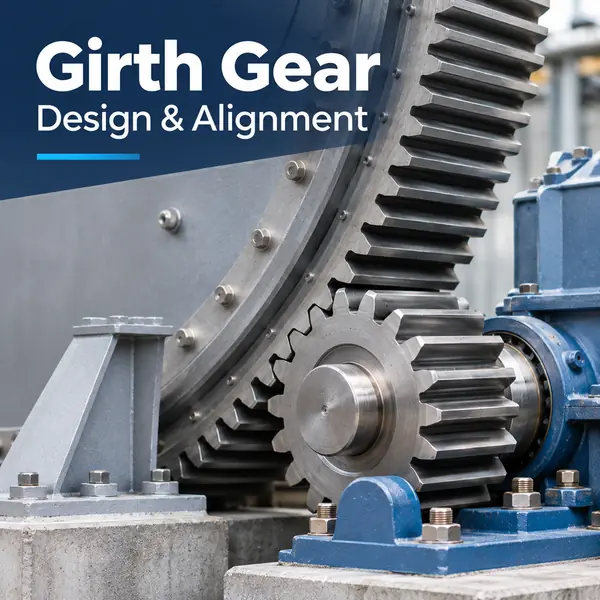
A girth gear is a large external ring gear mounted around the shell of rotating industrial equipment, such as ball mills, SAG mills and rotary kilns. It meshes with one or more pinions to transmit torque and drive the rotating shell at low speed.
Unlike gears inside an enclosed gearbox, a girth gear forms part of an open gear drive. Its performance depends on tooth accuracy, mounting runout, pinion alignment and the movement of the supporting shell under operating loads.
This guide covers girth gear design, manufacturing and inspection, including why a gear that meets factory tolerances may still develop uneven tooth contact after installation.
Key Takeaways
- Function: A girth gear meshes with one or more pinions to transmit torque and drive large rotating equipment at low speed.
- Design: One-piece gears eliminate segment joints, while segmented designs simplify transport and installation but require accurate joint alignment.
- Manufacturing: Cast or forged gear blanks are selected based on gear size, geometry, loading and manufacturing feasibility.
- Gear Meshing: Tooth accuracy alone cannot ensure proper contact. Installed runout, shell deformation and pinion alignment also affect meshing.
- Inspection: Factory checks verify gear geometry, while on-site checks assess backlash, runout and tooth contact after installation.
What Is a Girth Gear?
A girth gear is a large external ring gear mounted around the shell of rotating industrial equipment. It meshes with one or more pinions to transmit torque, typically in an open gear drive.
Unlike ring gears used inside gearboxes, girth gears are mounted directly or through supporting structures to large rotating drums or shells. They may be manufactured as one-piece rings or assembled from multiple segments, depending on equipment size and installation requirements.
Because the gear is connected to a large rotating structure, its operating alignment depends on both the gear’s geometry and the condition of its mounting and support system.
How Does a Girth Gear Work with a Pinion?
In a typical girth gear drive, the motor drives a smaller pinion through a gearbox. The pinion meshes with the girth gear, reducing rotational speed and increasing torque at the rotating drum or shell.
The gear ratio is calculated from the number of teeth on each gear:
Gear ratio (i) = Girth gear teeth / Pinion teeth
For a 240-tooth girth gear driven by a 24-tooth pinion, the gear ratio is 10:1. The girth gear rotates at one-tenth of the pinion speed, while the transmitted torque increases in proportion to the reduction ratio, subject to mechanical losses.
Correct meshing requires suitable center distance, backlash and pinion alignment. Incorrect center distance can change backlash, while angular misalignment may concentrate tooth contact toward one end of the gear face.
Where Are Girth Gears Used?
Girth gears are used in large rotating equipment that requires high torque at low speed, particularly in mining, cement production and industrial processing.
Equipment | Role and Operating Conditions |
Ball Mills | Drive the grinding drum under continuous rotation and varying grinding loads. |
SAG Mills | Transmit high torque under heavy, fluctuating loads during ore grinding. |
Rotary Kilns | Rotate the kiln shell while accommodating thermal expansion and changes in shell alignment. |
Industrial Dryers | Drive large drying drums during continuous operation, with temperature and load conditions varying by process. |
Although these machines use similar girth gear and pinion drives, their operating conditions differ. Grinding mills experience fluctuating loads, while rotary kilns must also accommodate thermal expansion and shell movement.
These differences affect gear design, mounting arrangements and alignment requirements. They should also be considered when selecting materials, manufacturing processes and inspection methods.
For applications suitable for forged ring blanks, a supplier combining custom forging and CNC machining can help maintain consistent requirements for machining allowances, mounting surfaces and dimensional inspection throughout production.
Girth Gear Design: One-Piece vs Segmented Construction
Girth gears are designed as one-piece rings or segmented assemblies, depending on gear size, manufacturing capacity and installation requirements.
One-piece gears eliminate segment joints but can be difficult to manufacture and transport at very large diameters. Segmented designs simplify handling and installation, although the joints require careful alignment and fastening.
Design | Main Advantage | Key Consideration |
One-piece | No segment joints | Manufacturing capacity and transport limits |
Segmented | Easier transport and installation of large gears | Joint alignment, fastening and tooth continuity |
For suitable one-piece designs, ring gear forgings may provide a starting blank, subject to diameter, section geometry and machining requirements.
For segmented girth gears, poor joint alignment can introduce pitch variation or tooth discontinuity, affecting load distribution as the pinion passes across the joint.
Girth gears may also use spur or helical teeth. The choice depends on loading, axial-force requirements and the overall drive arrangement.
Girth Gear Materials and Manufacturing Considerations
Girth gear material and manufacturing route depend on gear diameter, cross-section, operating loads, material requirements and production capacity. Cast steel is commonly used for large or segmented girth gears, particularly where complex sections make casting more practical.
For suitable one-piece steel girth gears, forged ring blanks offer an alternative to castings. Forging can refine the steel’s internal structure, while rolled ring forging can produce seamless rings with circumferential grain flow, depending on the material and deformation process.
Forging feasibility depends on ring diameter, section thickness, equipment capacity and machining requirements. The blank must provide sufficient machining allowance for mounting surfaces and gear teeth, accounting for dimensional variation and heat-treatment distortion where applicable.
The choice between cast and forged blanks should be based on material properties, geometry and manufacturing feasibility rather than assuming one process is always superior.
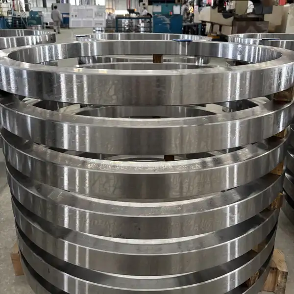
Real Manufacturing Example — Forged Steel Ring Blank
The photo shows a forged steel ring blank manufactured by Weforging. It is not a finished girth gear, but illustrates the ring forging capability that may be relevant to suitable one-piece gear designs.
For these applications, the choice between cast and forged blanks should be based on material requirements, geometry and manufacturing capability rather than assuming one process is always superior.
How Do Forged Ring Blanks Affect Final Girth Gear Accuracy?
A forged ring blank provides the starting geometry for machining, but its dimensional accuracy alone does not determine the accuracy of the finished girth gear.
Uneven machining allowance, heat-treatment distortion and unsuitable datum selection can affect the relationship between the gear teeth, mounting surfaces and rotational axis.
Before gear cutting, engineers should establish machining datums and verify the ring blank’s geometry and remaining machining allowance. During subsequent CNC machining, these datums must be maintained to control the relationship between the gear teeth, mounting surfaces and rotational axis.
If the blank is off-center or stock removal is uneven, some areas may lack sufficient material to achieve the required tooth and mounting-surface geometry. Identifying these issues early allows the machining plan to be reviewed before further processing.
Why Can a Girth Gear Pass Inspection but Still Have Poor Tooth Contact?
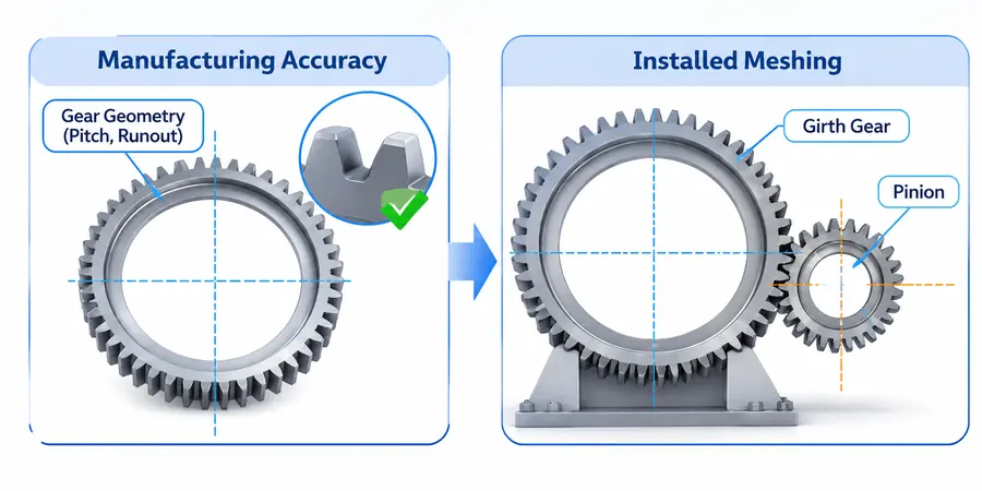
A girth gear can meet its specified manufacturing tolerances but still develop uneven tooth contact after installation. Factory inspection verifies tooth geometry, runout and mounting surfaces, while actual gear meshing also depends on pinion alignment, mounting accuracy and the rotating shell.
Unlike smaller gearbox gears, a girth gear is mounted on a large rotating structure that may change shape or position under operating loads and temperature variations. These changes can affect backlash and tooth contact even when the gear itself meets the drawing requirements.
Manufacturing Accuracy vs Installed Alignment
Manufacturing inspection typically checks tooth profile, pitch, radial runout and mounting surfaces against specified tolerances.
However, these measurements do not establish the final meshing condition. Incorrect center distance can alter backlash, while angular misalignment may concentrate contact toward one end of the tooth face. For segmented girth gears, poor joint alignment can also affect tooth continuity across the segment interfaces.
Installed alignment must therefore be checked as part of the complete girth gear and pinion drive.
How Shell Deformation Affects Gear Meshing
Large rotating shells can change shape or position under operating loads, temperature variations and support conditions. These changes may alter the girth gear’s position relative to the pinion, affecting backlash and tooth contact during rotation.
For example, excessive installed radial runout can cause backlash to vary around the gear circumference. Changes in the relative angular alignment of the gears may also shift contact toward one end of the tooth face, increasing local loading.
This is why girth gear inspection must distinguish manufacturing deviations from changes introduced by installation and operating conditions.
Girth Gear Inspection: Runout, Backlash and Tooth Contact
Girth gear inspection covers the manufactured gear geometry and the meshing condition after installation. The inspection items and acceptance criteria depend on the gear design and equipment requirements.
Inspection Item | What It Helps Verify |
Tooth profile and pitch | Tooth geometry and spacing against specified tolerances. |
Radial and axial runout | Radial variation of the gear and axial variation of specified faces relative to their datums. |
Backlash | Clearance between mating tooth flanks at selected rotational positions. |
Tooth contact pattern | Contact distribution across the tooth face and possible localized loading. |
Pinion alignment | Relative position and angular alignment of the girth gear and pinion. |
Factory inspection focuses on gear dimensions and geometric conformity. After installation, backlash, tooth contact and alignment should be checked at specified rotational positions to assess the assembled drive.
Acceptance limits must follow the gear drawings, equipment specifications and installation procedures. No single runout or backlash tolerance applies to every girth gear.
Why Does Machining Datum Selection Matter for Girth Gear Runout?
Girth gear runout is measured relative to a defined datum. A gear may meet individual machining tolerances, yet its final installed position can differ if the machining and mounting datums are not properly related.
For large ring gears, the mounting faces, locating diameters and tooth geometry must be controlled through a consistent datum strategy. Repositioning the workpiece between machining operations can introduce additional variation if these relationships are not maintained.
Inspection should therefore verify not only individual dimensions but also the geometric relationship between the gear teeth and the specified mounting datums.
Common Girth Gear Problems and Their Causes
Common girth gear problems include uneven tooth wear, vibration and tooth surface damage. Their causes may involve gear geometry, alignment, lubrication or operating loads rather than the gear teeth alone.
Problem | Possible Causes |
Uneven tooth wear | Misalignment, localized loading or inadequate lubrication. |
Excessive vibration | Runout, damaged teeth, loose mounting connections or drive misalignment. |
Abnormal tooth contact | Incorrect center distance, angular misalignment or changes in shell position. |
Pitting or scuffing | Pitting: repeated contact stress and surface fatigue. Scuffing: lubrication film breakdown and local overheating. |
Problems near segment joints | Joint misalignment, loose fasteners or discontinuity in tooth geometry. |
These symptoms do not identify a single cause. Before selecting corrective action, the assembled drive should be assessed using operating records, lubrication condition, alignment measurements and tooth contact inspection.
Conclusion
Girth gear performance depends on both manufacturing accuracy and the alignment of the assembled drive. A gear that meets its drawing tolerances may still experience uneven tooth contact if mounting conditions or pinion alignment are incorrect.
Material and manufacturing choices, including cast or forged blanks, should be evaluated against gear geometry, loading requirements and production feasibility.
For large girth gear drives, reliable operation requires more than an accurately manufactured gear. Mounting accuracy, runout, backlash and tooth contact must also be verified under the specified installation and operating conditions.