
Input Shaft: Function, Design and Manufacturing for Industrial Gearboxes
By Weforging Technical Team | Published November 12, 2026
An input shaft transfers torque from a motor or other drive source into an industrial gearbox. Depending on the design, a gearbox input shaft may include splines, keyways, bearing journals or an integral pinion.
Beyond transmitting torque, input shafts must withstand gear mesh forces and operate within the gearbox’s bearing and coupling arrangement. Even when shaft dimensions meet the drawing requirements, coupling misalignment can introduce additional loads during operation.
Understanding these conditions is important when evaluating input shaft design, common failure causes, material selection, forging, CNC machining and inspection requirements.
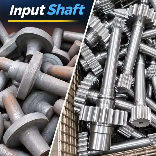
Key Takeaways
- Input shaft loading: An industrial gearbox input shaft may carry torsion and bending loads, depending on gear position and bearing support.
- Component vs. assembly alignment: A shaft that meets drawing tolerances can still experience additional loads from coupling misalignment.
- Forging and machining: Forged blanks may be suitable for heavy-duty or large stepped shafts, but the manufacturing route depends on geometry, material and production volume.
- Inspection: Bearing fits, datum-related geometry and first-part results should be verified against the OEM drawing before batch production.
What Is an Input Shaft?
An input shaft is the rotating shaft that transfers power from a motor or drive system into a gearbox. In industrial gearboxes, it commonly connects to the driving equipment through a coupling and delivers torque to the first gear stage.
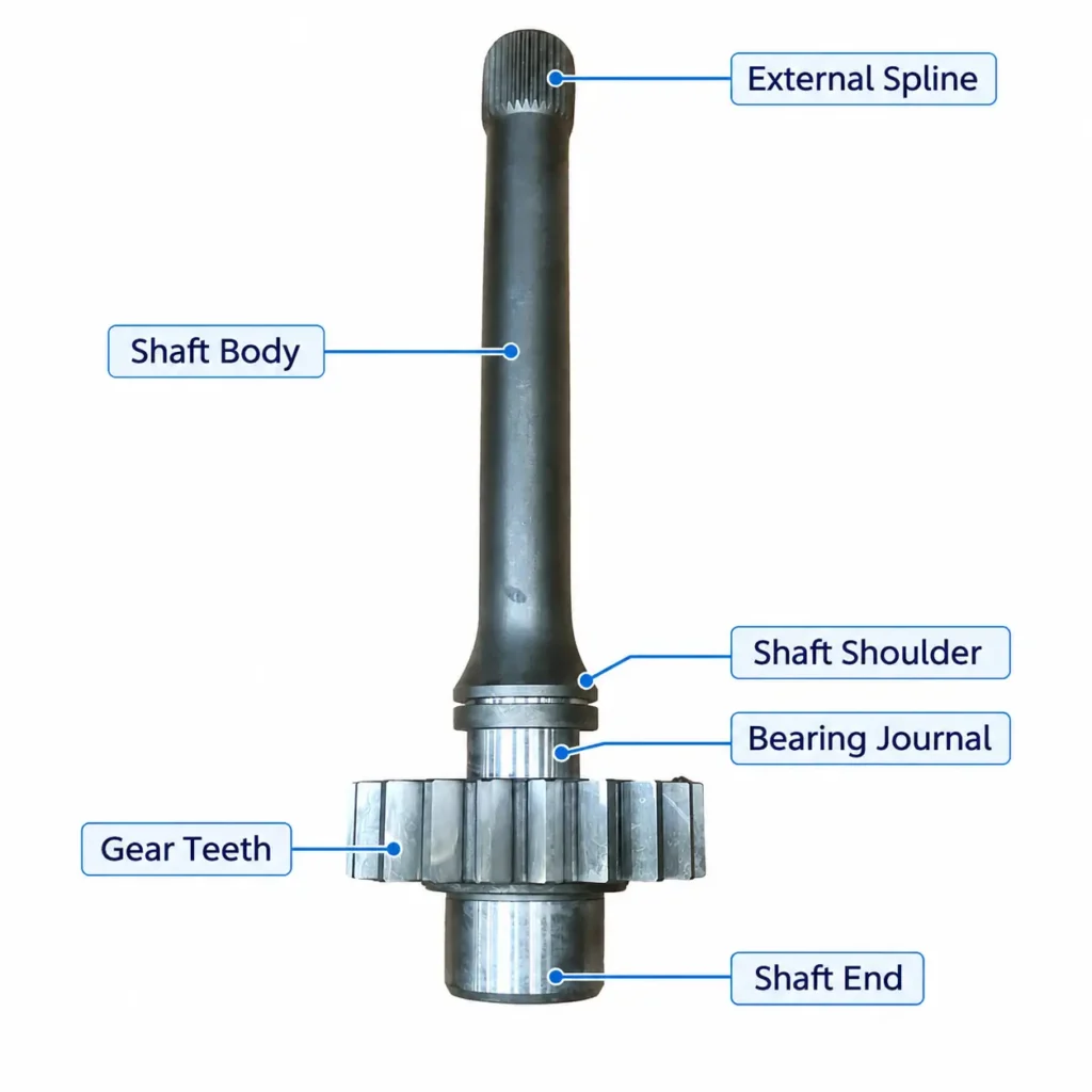
An input shaft is defined by its function rather than a fixed shape. Depending on the gearbox design, it may include external splines, keyways, bearing journals, shaft shoulders or an integral pinion.
Splines and keyways transmit torque, bearing journals support and locate the rotating shaft, and shaft shoulders position bearings or other mounted components. The arrangement of these features depends on the transmitted load, bearing layout and assembly requirements.
How Does an Input Shaft Work in an Industrial Gearbox?
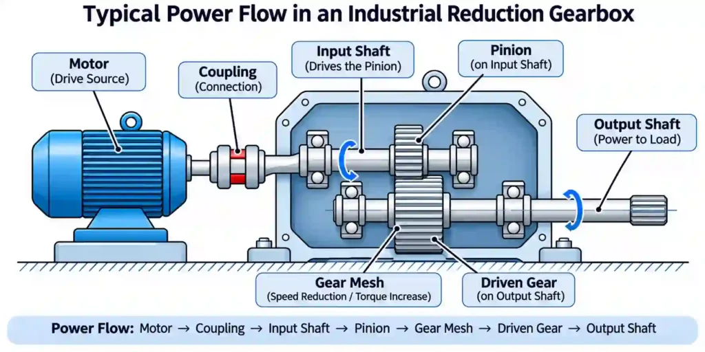
In an industrial gearbox, the input shaft transfers rotational power from the driving equipment to the gear train. In a typical motor-driven reducer, power passes through the coupling and input shaft to the first gear stage, then through the remaining gear stages to the output shaft.
The input shaft may drive an integral pinion or a separately mounted gear. In a reduction gearbox, gear ratios reduce rotational speed while increasing torque at the output, allowing for transmission losses.
When gears are mounted on or integrated with the input shaft, gear mesh forces also create loads that must be supported by the shaft bearings. Depending on the gear arrangement and bearing positions, these forces can produce shaft bending in addition to torsion.
The input shaft works alongside the gears, bearings and other industrial gearbox parts that support torque transmission.
Input Shaft Torque and Power
For steady-state operation, input shaft torque can be calculated from transmitted power and rotational speed:
T = 9550 × P / n
Where:
- T= Torque (N·m)
- P= Transmitted power (kW)
- n= Rotational speed (rpm)
For example, an input shaft transmitting 30 kW at 1,500 rpm carries approximately 191 N·m of torque.
This value represents steady-state torque, not the maximum design load. Startup torque, shock loads, cyclic loading and the applicable service factor must also be considered when evaluating shaft strength and fatigue life.
Input Shaft vs. Output Shaft: What Is the Difference?
The input shaft receives power from the drive source, while the output shaft delivers power from the gearbox to the driven equipment. In a typical reduction gearbox, the input shaft operates at a higher speed and lower torque than the output shaft. In a speed-increasing gearbox, the output shaft typically rotates faster and carries lower torque.
Feature | Input Shaft | Output Shaft |
Function | Power input to the gearbox | Power delivery from the gearbox |
Speed in a reduction gearbox | Typically higher | Typically lower |
Torque in a reduction gearbox | Typically lower | Typically higher |
Typical connections | Motor coupling or splined connection | Coupling, hub or driven equipment |
Key design considerations | Input torque, gear forces, bearing support and coupling alignment | Output torque, external loads, bearing support and connection geometry |
Although both shafts require suitable material properties and dimensional accuracy, their design requirements differ. Shaft selection must account for actual loads, bearing arrangements and connection geometry rather than material grade or diameter alone.
Common Input Shaft Designs and Applications
Industrial gearbox input shafts are designed around their torque-transmitting connections, gear arrangements and bearing support. Common configurations include splined or keyed shafts and integral pinion shafts. The appropriate design depends not only on transmitted torque but also on assembly requirements, gear loading and shaft geometry.
Splined and Keyed Input Shafts
Splined input shafts transmit torque through mating spline teeth, while keyed shafts use a key and keyway to connect the shaft to a hub or coupling.
Splines provide multiple potential load-bearing contact surfaces, but the load is not necessarily distributed evenly across all teeth. Fit, alignment and manufacturing accuracy affect contact conditions, particularly under reversing or fluctuating torque.
Keyed connections can be suitable for simpler shaft-hub arrangements, provided the key, keyway and shaft section meet the required loading and fatigue conditions. The choice should follow the connection design rather than an assumption that one arrangement is always stronger.
For drawing-specific spline geometry, Weforging supplies custom splined shafts for industrial transmission applications.
Integral Pinion Input Shafts
An integral pinion input shaft combines the driving gear and shaft into one component, eliminating the need for a separate gear mounting interface.
However, removing the gear-to-shaft connection does not eliminate manufacturing challenges. The pinion teeth, bearing journals and shaft datum axis must maintain the specified geometric relationships.
This design can be suitable where gear positioning and a compact transmission arrangement favor an integrated component, but the manufacturing route must account for gear machining, heat treatment and finishing requirements.
Input Shaft Design for Heavy-Duty Applications
Input shafts in industrial reducers, mining machinery and conveyor drives may operate under fluctuating torque, frequent starts and gear mesh loads.
Two shafts with similar rated torque can require different designs if their shock loading, bearing spans or gear positions differ. These conditions affect bending loads, fatigue requirements and stress concentrations at shaft shoulders and diameter transitions.
For heavy-duty applications, shaft diameter alone is not a sufficient selection criterion. Geometry, bearing support, material condition and the actual duty cycle must be considered together.
What Causes Input Shaft Failure?
Input shaft failures may involve fatigue cracking, spline wear, bearing journal damage or permanent bending. These conditions can result from different combinations of operating loads, geometry, material condition and assembly factors.
For example, a crack near a shaft shoulder may be associated with cyclic bending and local stress concentration. Bearing journal wear may involve an unsuitable fit or movement between the bearing and shaft.
The table below identifies common symptoms, possible causes and the checks needed to investigate them.
Failure or Symptom | Possible Causes | Engineering Checks |
Fatigue cracking | Cyclic bending, torsional loading, stress concentration | Crack origin, fillet geometry, load history |
Spline wear | Misalignment, fretting, inadequate lubrication where required | Spline contact, fit, surface condition |
Bearing journal damage | Incorrect fit, bearing movement, abnormal loads | Journal dimensions, fit and fretting evidence, bearing condition |
Excessive vibration | Misalignment, unbalance, bearing or gear defects | Runout, assembly alignment, vibration data |
Permanent bending | Overload or impact loads exceeding the shaft’s yield capacity | Shaft straightness, material condition, load history |
Damage patterns help guide an investigation, but they do not establish the root cause on their own. Load history, material condition, shaft geometry and gearbox assembly may all need to be examined.
How Do Coupling Misalignment and Bearing Support Affect Input Shaft Performance?
An input shaft can meet its drawing tolerances and still operate under unexpected loads. In a motor-driven gearbox, the motor and input shaft are supported by separate bearing systems, and their alignment depends on the installed assembly.
The coupling, bearing arrangement and gear position therefore affect the loads acting on the shaft—not just its manufactured dimensions.
How Does Coupling Misalignment Affect Input Shaft Loading?
Parallel offset or angular misalignment between the motor and gearbox shafts can produce reaction forces at the coupling. Flexible couplings accommodate specified misalignment, but they do not necessarily eliminate the resulting forces and moments.
When bearing damage or vibration recurs, coupling alignment should be examined alongside bearing condition, shaft geometry and operating loads.
Why Does Bearing Support Geometry Matter?
Bearing span and gear position determine how gear mesh forces are carried by the shaft. A gear located between two bearings creates a different bending condition from an overhung gear positioned outside the bearing span.
These relationships are established by the gearbox design. Shaft inspection can verify specified journal dimensions and geometric tolerances, but it cannot correct misaligned housing bores or an unsuitable bearing arrangement.
When Should an Input Shaft Be Forged?
A forged input shaft blank may be suitable for heavy-duty applications, large stepped geometries or designs requiring a specified forged material condition.
For simpler shafts, machining from bar stock may be more economical. Where substantial diameter changes would otherwise require extensive material removal, a forged preform may reduce machining waste. The choice also depends on production quantity and forging costs.
Forging alone does not guarantee better fatigue performance. Steel quality, heat treatment, surface condition and stress concentrations remain important.
Machining allowances must also be established before forging. Bearing journals and other critical surfaces need sufficient material for finishing, particularly when heat treatment distortion must be corrected.
For heavy-duty 42CrMo4 input shafts, forging followed by quenching and tempering may be specified to achieve the required mechanical properties, with tensile and yield strength verified against the applicable specification.
Weforging provides custom forging for industrial components, with subsequent machining according to the agreed production scope.
Input Shaft Materials and Heat Treatment
Industrial gearbox input shafts are commonly made from medium-carbon or alloy steels. Material selection depends on transmitted torque, bending loads, fatigue requirements, shaft size and heat treatment.
Common options include AISI 1045 for suitable general shaft applications, AISI 4140 or 42CrMo4 where higher strength and hardenability are required, and AISI 4340 for certain demanding applications.
Quenching and tempering may be used to achieve specified strength and toughness, while case-hardening steels may be selected for gears or splines requiring wear-resistant surfaces and suitable core properties.
Material grades are not directly interchangeable. Selection must account for applicable specifications, hardenability and required mechanical properties.
Why Are Forging and Quenching & Tempering Important for 42CrMo4 Input Shafts?
For heavy-duty industrial gearbox input shafts made from 42CrMo4 steel, tensile strength and yield strength must meet the specified mechanical requirements. Forging followed by quenching and tempering (Q&T) is a suitable manufacturing route for stepped shafts subjected to demanding loads.
For this 42CrMo4 input shaft application, the specified mechanical properties after Q&T are a tensile strength greater than 850 MPa and a 0.2% proof strength of at least 750 MPa.
Forging provides the required shaft preform, while Q&T develops the specified combination of strength and toughness. However, completing these processes alone does not confirm compliance. Tensile testing, heat treatment records and material traceability should be used to verify the required properties according to the agreed inspection requirements.
How Can Heat Treatment Distortion Affect Input Shaft Geometry?
Heat treatment can cause bending, runout changes or dimensional variation in long or stepped input shafts due to uneven heating, cooling and residual stress redistribution.
These changes may affect bearing journal alignment and other critical geometric relationships. A shaft that meets dimensional requirements before heat treatment may no longer meet its final geometric tolerances afterward.
To manage this risk, manufacturers may retain finishing allowances, inspect shaft straightness after heat treatment and finish-machine critical surfaces as required.
The machining sequence should therefore account for heat treatment distortion and the specified final tolerances.
Input Shaft Machining: Datums, Fits and Critical Tolerances
Input shaft machining must control both individual dimensions and the relationships between functional features. Bearing journals, shaft shoulders, splines and gear features may be produced in different operations, but their final geometry must meet the same OEM drawing.
The machining plan should establish suitable datums before selecting setups and finishing operations.
Bearing Journals and Shaft Shoulders
Bearing journals require the specified fit, surface finish and geometric accuracy. Shaft shoulders may provide axial bearing location and, where specified, must meet face runout or perpendicularity requirements.
A journal diameter within tolerance does not establish whether its relationship to another bearing seat or shaft feature is correct.
Maintaining Alignment Across Machining Setups
Multiple machining setups can introduce alignment errors when an input shaft is located from different reference surfaces.
For example, bearing journals may meet their individual diameter tolerances while a separately machined spline or gear feature fails its specified runout or positional requirement.
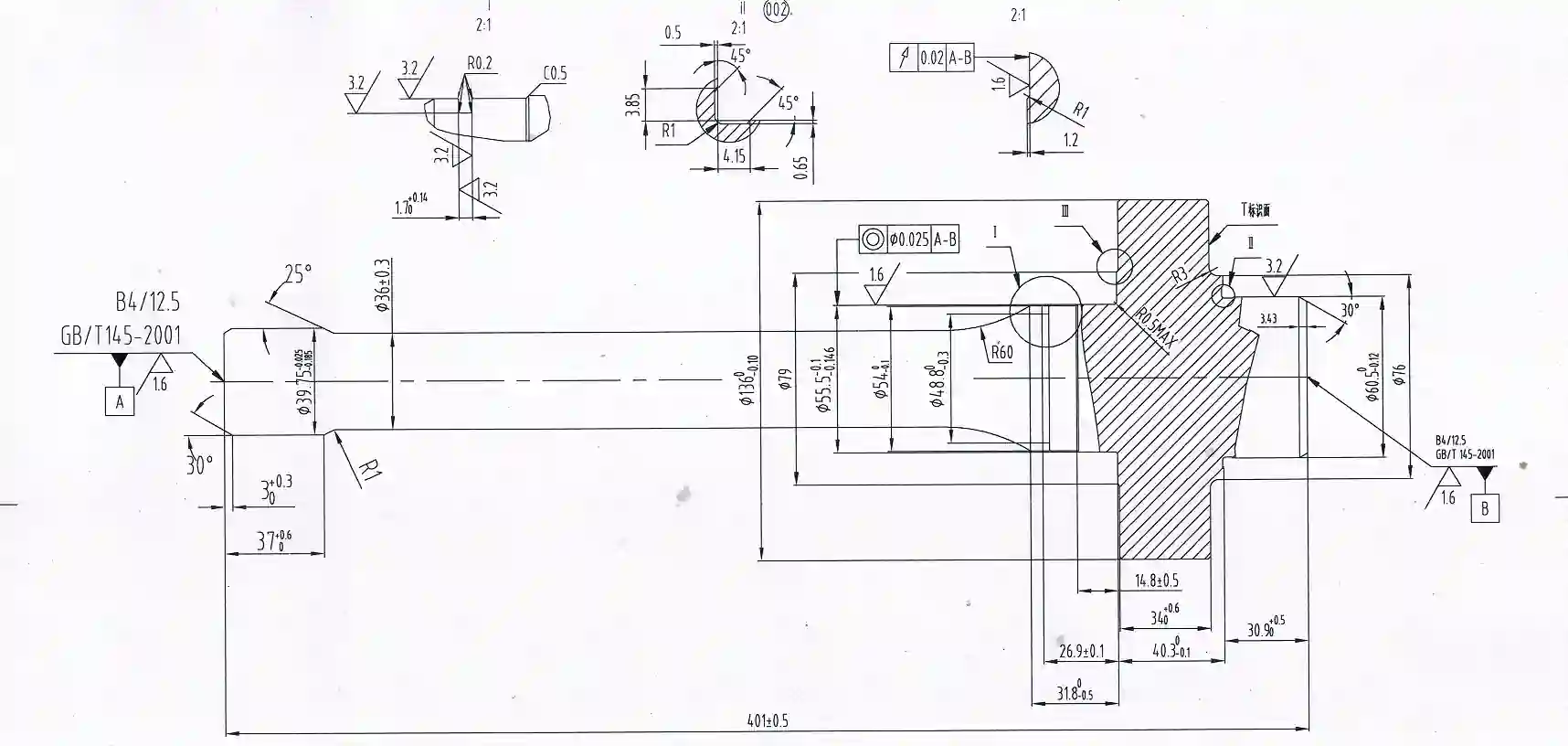
Machining between centers or using controlled reference features can help maintain alignment where appropriate. The final inspection must verify the geometric relationships defined on the OEM drawing.
Weforging provides CNC machining services for custom forged and machined transmission components.
What Should Be Verified Before Input Shaft Production?
Before repeat production of an industrial gearbox input shaft, the manufacturer should confirm that the material, manufacturing process and first-part inspection results meet the agreed requirements.
Verification should focus on features affecting bearing fit, torque transmission and gearbox assembly, rather than applying the same inspection checklist to every shaft design.
Material and Heat Treatment Verification
Material verification may include steel grade confirmation, heat-number identification, chemical analysis and mechanical testing according to the project specification.
Where heat treatment is required, hardness, mechanical properties and relevant dimensional changes should be checked against the agreed acceptance criteria.
Where tensile and yield strength are specified, the inspection plan should define the applicable acceptance values, test specimen location and required mechanical test records.
First-Part Inspection of Critical Input Shaft Features
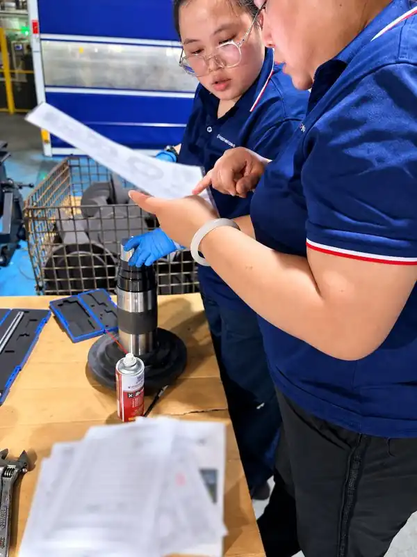
First-part inspection confirms whether the selected manufacturing process can produce an input shaft that meets the drawing requirements.
Checks may include bearing journal dimensions, shoulder geometry, spline features and specified runout or positional tolerances.
At Weforging, first-part verification can involve operator checks, independent inspection and laboratory testing as required. The results are reviewed before the process is released for repeat production.
Inspection Records and Batch Traceability
For repeat OEM orders, inspection records help verify consistency between production batches.
Where required, material heat numbers, heat treatment batches and inspection results can be linked to the corresponding components. These records provide a reference for investigating dimensional or material variations in subsequent production.
What Should OEM Buyers Specify for Custom Input Shafts?
For a custom input shaft, the drawing and operating conditions should be reviewed together before quotation. Two shafts with similar dimensions may require different materials, manufacturing routes or inspections because of differences in torque, bearing support or duty cycle.
The following information helps define the manufacturing and inspection scope.
Requirement | Information to Provide |
Material | Steel grade, material standard and required properties |
Operating conditions | Torque, speed, duty cycle, startup loads and relevant gear or external loads |
Shaft geometry | Diameters, shoulders, splines, keyways and critical connection features |
Heat treatment | Required process, hardness and specified mechanical or surface properties |
Tolerances | Bearing journal fits, GD&T, datum references and surface finish |
Spline requirements | Spline standard, tooth geometry, fit and inspection requirements |
Inspection | Critical characteristics, inspection reports and acceptance criteria |
Supply condition | Forged blank, rough-machined or finished input shaft |
Order details | Order quantity, annual demand and delivery requirements |
Unspecified bearing fits, spline requirements or datum references should be clarified before manufacturing rather than replaced with assumed standard tolerances.
Weforging supplies custom forged and machined components for industrial gearboxes. Related capabilities include transmission and gear shaft manufacturing, with delivery conditions agreed according to the OEM drawing.
Input Shaft Design and Manufacturing Reliability
An industrial gearbox input shaft must carry the required loads while maintaining the geometry needed for bearing support and torque transmission. Reliable operation depends on both component quality and the alignment of the assembled drive system.
For forged and machined input shafts, material condition, machining datums, heat treatment distortion and inspection requirements should be addressed before production.
Weforging manufactures custom forged and CNC-machined transmission components to OEM drawings. Share your shaft drawing and operating requirements to review manufacturing feasibility, critical tolerances and delivery condition.