
CNC Surface Finish Guide: Ra Values, Standards and Applications
CNC surface finish plays a critical role in the performance, reliability, and service life of machined components. In industries such as mining equipment, hydraulic systems, industrial gearboxes, agricultural machinery, and heavy equipment manufacturing, surface finish requirements are often specified directly on engineering drawings.
A proper surface finish improves sealing performance, reduces friction and wear, enhances fatigue resistance, and ensures stable assembly fit. At the same time, achieving a lower surface roughness usually requires additional machining operations and higher manufacturing costs.
This guide explains common Ra values, surface finish standards, machining capabilities, inspection methods, and how surface finish affects CNC machined parts in real industrial applications.
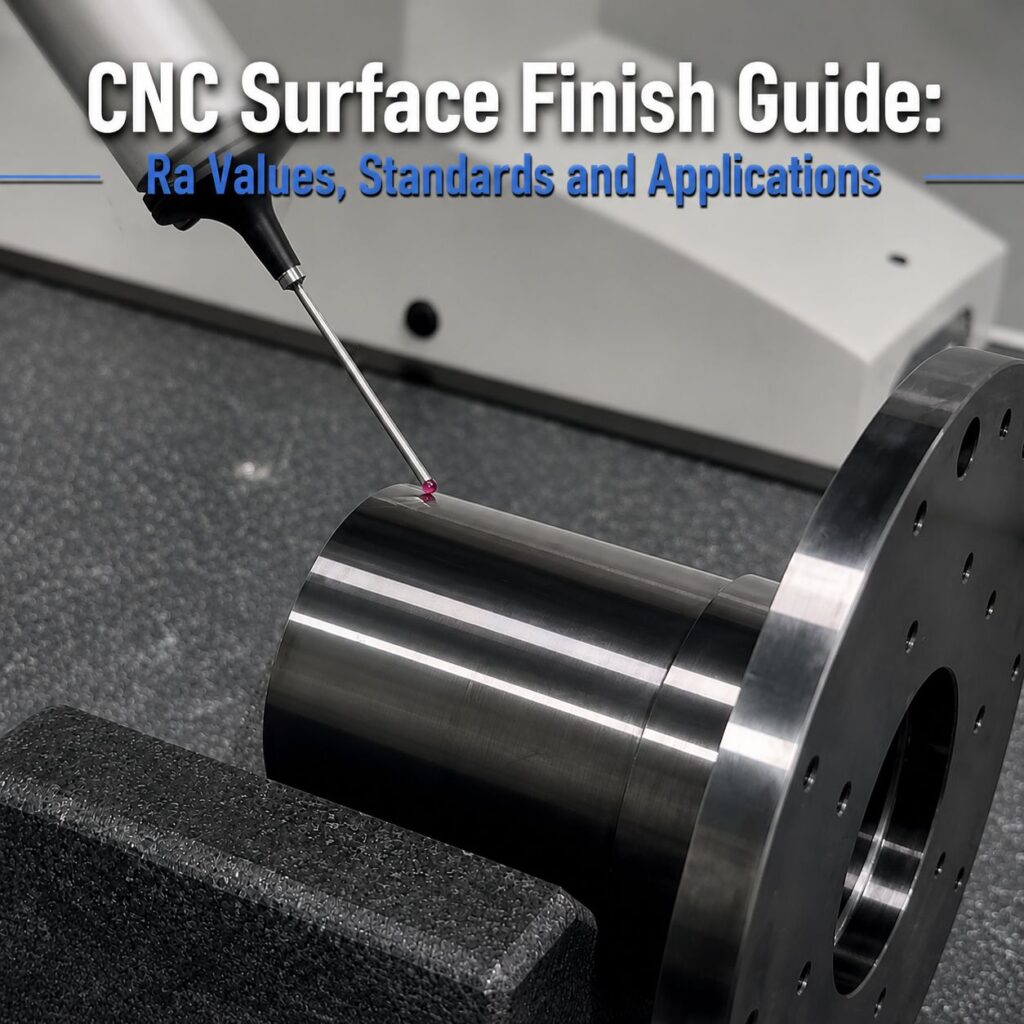
What Is CNC Surface Finish?
CNC surface finish describes the texture and overall condition of a surface produced by machining. Although a machined part may look smooth, microscopic peaks, valleys, tool marks, and other irregularities remain on its surface.
The final finish is influenced by the machining process, cutting speed, feed rate, tool geometry, tool wear, machine rigidity, material condition, and coolant control.
In CNC machining, Ra (Roughness Average) is the most commonly specified parameter for evaluating surface roughness. A lower Ra value generally indicates a smoother surface, but it may also require additional machining time or secondary finishing operations.
For this reason, the required surface finish should normally be selected according to the functional needs of the component rather than simply specifying the lowest possible Ra value.
Surface Finish vs Surface Roughness
Although the two terms are often used interchangeably, they represent different concepts.
| Item | Surface Roughness | Surface Finish |
|---|---|---|
| Definition | Microscopic texture of a surface | Overall surface quality |
| Measurement | Ra, Rz, Rt values | Includes roughness, waviness and lay |
| Typical Use | Inspection and quality control | Engineering specifications |
| Drawing Requirement | Roughness parameter | Complete surface requirement |
Surface roughness is only one component of surface finish. Surface finish also includes waviness, texture direction, and other characteristics that influence functional performance.
For most CNC machined components, engineering drawings specify an Ra value to define the required surface finish level.
CNC Surface Finish Chart: Ra, Microinch and N Grade
Surface finish values may be specified in micrometers (μm), microinches (μin), or roughness grades. The following surface finish chart provides commonly referenced approximate equivalents.
| Ra μm | Ra μin | N Grade | General Finish Level |
|---|---|---|---|
| 12.5 | 500 | N10 | Rough machined |
| 6.3 | 250 | N9 | Rough machined |
| 3.2 | 125 | N8 | Standard machined |
| 1.6 | 63 | N7 | Fine machined |
| 0.8 | 32 | N6 | Precision finish |
| 0.4 | 16 | N5 | Fine precision finish |
| 0.2 | 8 | N4 | Very fine finish |
| 0.1 | 4 | N3 | Superfinish |
This chart is useful when comparing specifications written in different units. For example, Ra 3.2 μm corresponds to approximately 125 μin, while Ra 0.8 μm corresponds to approximately 32 μin.
Actual acceptance should always follow the engineering drawing and applicable measurement standard.
Common Ra Values and Their Applications
Different components require different surface finish levels depending on their function.
| Ra Value | Typical Surface Quality | Common Applications |
|---|---|---|
| Ra 6.3 μm | Rough finish | Structural parts, brackets |
| Ra 3.2 μm | Standard finish | General CNC machined parts |
| Ra 1.6 μm | Fine finish | Gear blanks, shaft journals |
| Ra 0.8 μm | Precision finish | Bearing seats, hydraulic components |
| Ra 0.4 μm | High precision finish | Sealing surfaces |
| Ra 0.2 μm | Ultra-fine finish | Precision hydraulic systems |
For most industrial applications, Ra 3.2 μm offers a practical balance between manufacturing cost and functional performance.
CNC Surface Finish Chart
The achievable surface finish depends largely on the machining process used.
| Manufacturing Process | Typical Ra Range |
|---|---|
| Rough Turning | 6.3 – 12.5 μm |
| Finish Turning | 1.6 – 3.2 μm |
| Milling | 1.6 – 6.3 μm |
| Surface Grinding | 0.4 – 1.6 μm |
| Cylindrical Grinding | 0.2 – 0.8 μm |
| Honing | 0.1 – 0.8 μm |
| Lapping | 0.05 – 0.4 μm |
As the required Ra value decreases, machining complexity, inspection requirements, and production costs generally increase.
For example, achieving Ra 0.8 μm may require precision grinding, while Ra 0.4 μm or below often requires honing or lapping operations.
Surface Finish Symbols on Engineering Drawings
Surface finish requirements are commonly indicated using ISO 1302 symbols.
These symbols communicate important information such as:
- Required Ra value
- Material removal requirements
- Surface lay direction
- Additional machining instructions
Examples include:
| Drawing Requirement | Typical Application |
|---|---|
| Ra 3.2 | General machining surfaces |
| Ra 1.6 | Precision fits |
| Ra 0.8 | Bearing seats |
| Ra 0.4 | Hydraulic sealing surfaces |
Understanding surface finish symbols helps manufacturers select the appropriate machining and inspection methods before production begins.
What Surface Finish Can CNC Machining Achieve?
Different machining processes leave different surface textures. The achievable Ra value depends on the cutting method, tooling condition, machine stability, and material being machined.
In most cases, lower surface roughness requires additional finishing operations, which increases machining time and manufacturing cost.
CNC Turning
CNC turning is commonly used for shafts, sleeves, flanges, and bearing housings. Under normal machining conditions, turning can typically achieve a surface finish between Ra 1.6 and 6.3 μm.
For many general-purpose machined parts, a finish of Ra 3.2 μm is sufficient without additional secondary processing.
CNC Milling
Milling is widely used for structural components, equipment housings, and gear blanks. Depending on the cutter geometry and machining parameters, surface finishes between Ra 1.6 and 3.2 μm are commonly achieved.
Milled surfaces often provide a good balance between machining efficiency and dimensional accuracy.
Grinding
When tighter tolerances and smoother surfaces are required, grinding is often used after CNC machining. Typical grinding operations can achieve Ra 0.4 to 1.6 μm, making them suitable for bearing seats, shaft journals, and precision fit surfaces.
Many rotating components rely on grinding to improve both surface quality and assembly performance.
Honing and Lapping
Honing and lapping are used when extremely smooth surfaces are required. These finishing processes can achieve surface finishes as low as Ra 0.05 to 0.8 μm.
Typical applications include hydraulic cylinders, sealing surfaces, precision valve components, and other parts where leakage control or low friction is critical.
Key Takeaway
Lower Ra values do not always mean better performance. The appropriate surface finish should be selected according to the component’s function, drawing requirements, and operating conditions. For many industrial components, Ra 1.6–3.2 μm already provides an effective balance between performance and manufacturing cost.
How Surface Finish Affects Part Performance
Surface finish is a functional requirement rather than simply a cosmetic one. Selecting an appropriate roughness can influence how mating surfaces contact each other and how a component performs over time.
Four areas are particularly important:
Sealing: Excessive surface irregularities may create leakage paths on hydraulic or pneumatic sealing surfaces.
Wear: Rough mating surfaces can increase friction and accelerate wear during operation.
Fatigue: Machining marks and surface irregularities can contribute to local stress concentration, particularly on cyclically loaded components.
Fit and assembly: Surface condition can influence bearing fits, shaft interfaces, and other precision assemblies.
The required Ra value should therefore reflect the operating conditions and function of the specific surface.
How Surface Finish Is Measured
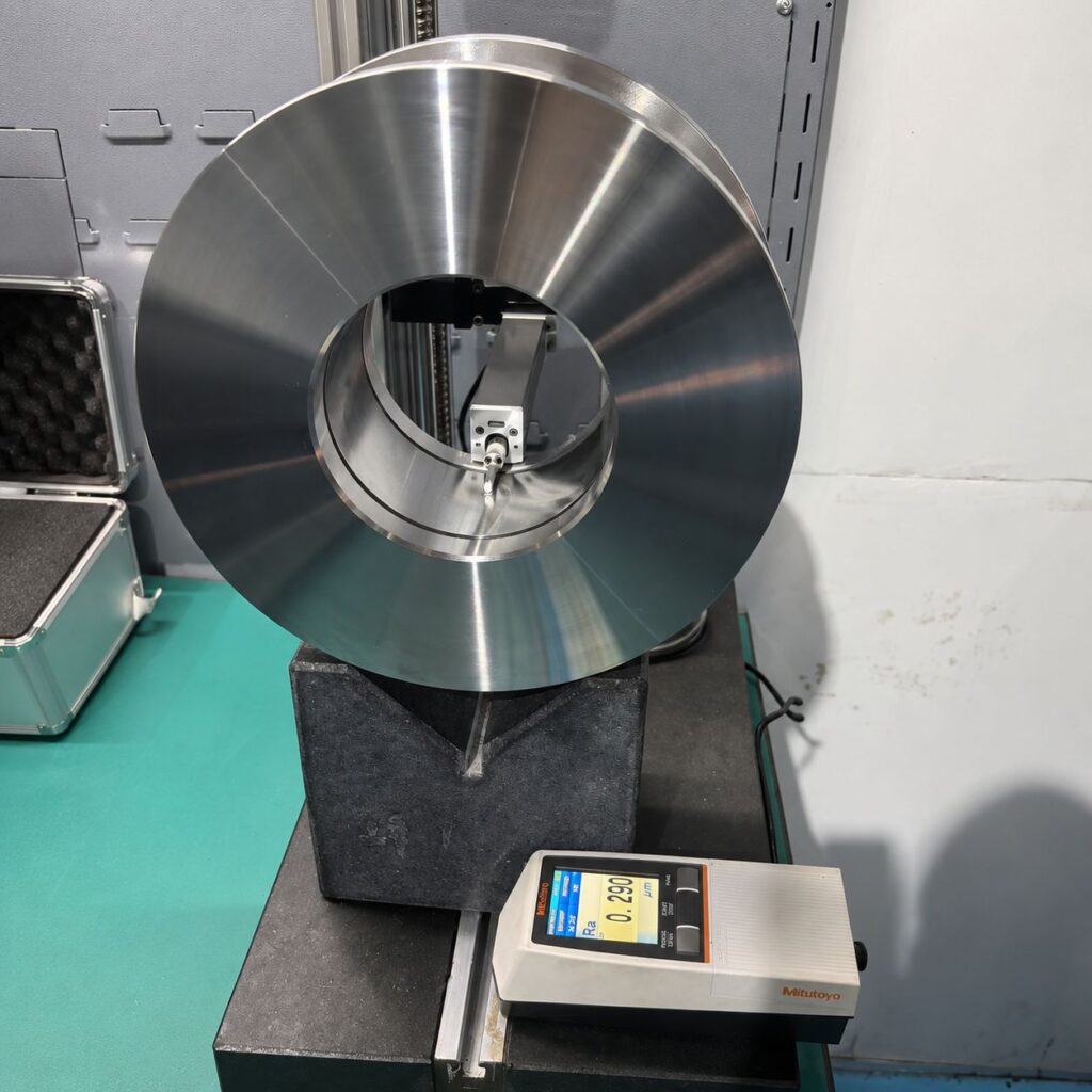
Surface roughness is commonly measured using a surface roughness tester or profilometer. A contact-type instrument moves a stylus across the surface and records variations in the surface profile.
A typical inspection process includes:
- Cleaning the measurement area
- Selecting the correct measurement parameters
- Calibrating or verifying the instrument
- Measuring specified locations
- Recording the Ra or other required values
- Comparing the results with drawing requirements
Measurement direction, cutoff length, sampling length, and surface condition can affect the result. For critical OEM components, these conditions should be defined according to the applicable drawing or inspection standard.
Recommended Surface Finish by Application
Surface finish should be selected according to the function of the machined area rather than applying one roughness value to the entire component.
| Application | Typical Ra Range |
|---|---|
| General Machined Surfaces | Ra 3.2–6.3 μm |
| Gear Blank Faces | Ra 1.6–3.2 μm |
| Shaft Journals | Ra 0.8–1.6 μm |
| Bearing Seats | Ra 0.4–0.8 μm |
| Precision Rotating Surfaces | Ra 0.4–1.6 μm |
| Hydraulic / Sealing Surfaces | Ra 0.2–0.8 μm |
These values are typical references rather than universal specifications. Load, speed, lubrication, seal design, material, dimensional tolerance, and subsequent surface treatment can all change the required finish.
The engineering drawing should remain the primary basis for production and inspection.
How to Choose the Right CNC Surface Finish
The smoothest surface is not automatically the best choice. A lower Ra requirement usually means tighter process control, longer machining time, and potentially additional finishing operations.
Before specifying a surface finish, consider:
- Is the surface functional or non-critical?
- Does it contact a bearing, seal, or mating component?
- Is friction or wear important?
- Is the component exposed to cyclic loading?
- Can standard CNC machining achieve the requirement?
- Will grinding, honing, or lapping be necessary?
For general machined surfaces, Ra 3.2 may be sufficient. Critical bearing, sealing, and precision fit areas may require Ra 1.6, Ra 0.8, or lower depending on the application.
Conclusion
CNC surface finish affects dimensional fit, friction, sealing, wear, and the long-term performance of machined components. Common specifications range from Ra 3.2 μm for general machining to Ra 0.8 μm or lower for precision bearing and sealing surfaces.
The appropriate value depends on the function of each surface and the machining process used to produce it.
Rather than applying unnecessarily fine finishes across an entire component, manufacturers and engineers can evaluate each functional area individually and select a practical combination of machining method, Ra requirement, dimensional tolerance, and inspection method.