Precision Rotor Core Manufacturing Case
Project Snapshot
| Item | Details |
|---|---|
| Industry | Robotics & Industrial Automation |
| Component | Precision Rotor Core |
| Material | Low Carbon Steel |
| Heat Treatment | Normalizing + Stress Relief Annealing |
| Surface Finish | Ra 0.29 μm |
| Inspection | CMM Inspection |
| Production Type | Batch Manufacturing |
Project Overview
The Challenge Behind a Thin-Wall Rotor Core
Rotor cores used in robotics and industrial automation systems require more than dimensional accuracy. Stable magnetic performance, geometric consistency and repeatable assembly results are equally important.
For this project, the customer required a batch of thin-wall rotor cores with strict concentricity requirements and an internal bore surface finish of Ra 0.8 μm.
Although the geometry appeared straightforward, dimensional stability throughout machining, heat treatment and inspection became the primary engineering challenge.
Engineering Challenge
Producing a qualified rotor core required balancing customer performance expectations with manufacturing realities. The challenge was not simply achieving the drawing dimensions, but maintaining dimensional stability throughout the entire production process.
| Customer Requirement | Manufacturing Challenge |
|---|---|
| Thin-wall structure | Deformation during machining and heat treatment |
| Tight concentricity | Rotor balance and assembly risks |
| Stable magnetic performance | Material and heat treatment consistency |
| Ra 0.8 μm surface finish | Stable machining capability |
| Batch consistency | Process repeatability and dimensional control |
These requirements made dimensional stability more critical than dimensional accuracy alone.
Material Selection
Material selection was driven by magnetic performance requirements rather than mechanical strength alone.
The selected low-carbon steel offered:
✓ Stable magnetic characteristics
✓ Good machinability
✓ Predictable heat treatment response
✓ Reliable batch production consistency
✓ Cost-effective manufacturing capability
Material certificates were verified before production and full traceability was maintained throughout the project.
Heat Treatment Strategy
Why Two Heat Treatment Cycles Were Used
Instead of relying on a single thermal process, two separate heat treatment stages were introduced.
| Process | Purpose |
|---|---|
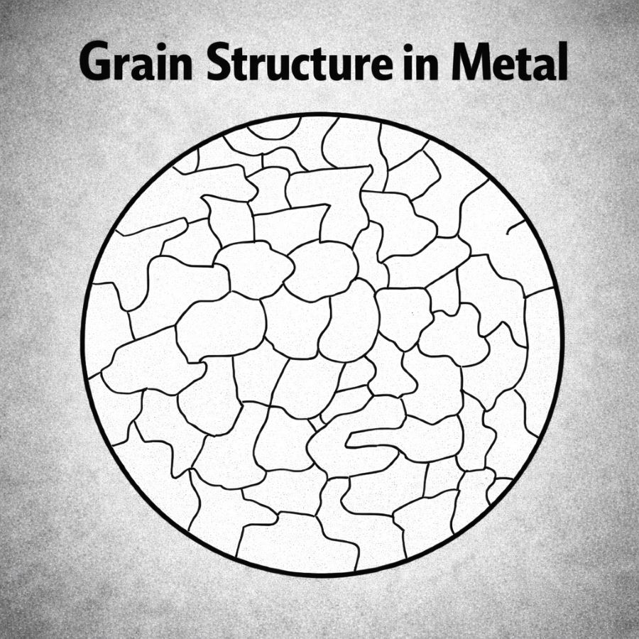
| Normalizing | Refine grain structure and improve material uniformity |
| Stress Relief Annealing | Remove residual machining stress before final machining |
The second heat treatment stage was added specifically because of the thin-wall geometry and strict concentricity requirements.
This significantly reduced the risk of dimensional movement later in production.
Manufacturing Process
The manufacturing process was designed around stability rather than machining speed.
Material Verification
        ↓
Rough Machining
        ↓
Normalizing
        ↓
Semi-Finish Machining
        ↓
Stress Relief Annealing
        ↓
Final CNC Machining
        ↓
22°C CMM Inspection
        ↓
Final Verification
Key Features Controlled
- Internal Bore Accuracy
- Concentricity
- Surface Finish
- Circularity
- Dimensional Consistency
Surface Finish Verification
The internal bore was identified as a critical assembly feature on the drawing.
| Feature | Requirement | Actual Result |
|---|---|---|
| Surface Finish | Ra 0.8 μm | Ra 0.29 μm |
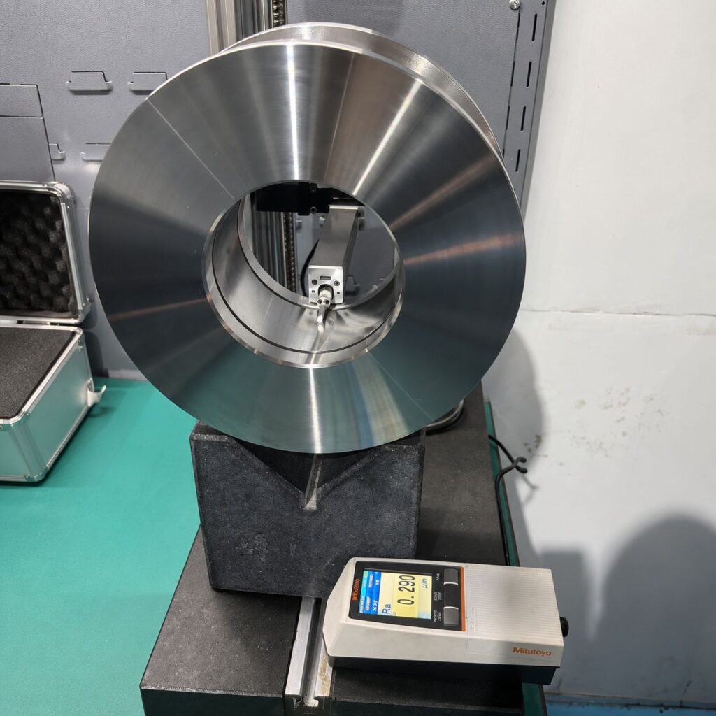
Final measurements were completed using a Mitutoyo surface roughness tester. The measured value of Ra 0.29 μm exceeded the customer’s specification and demonstrated stable machining performance.
What CMM Inspection Revealed
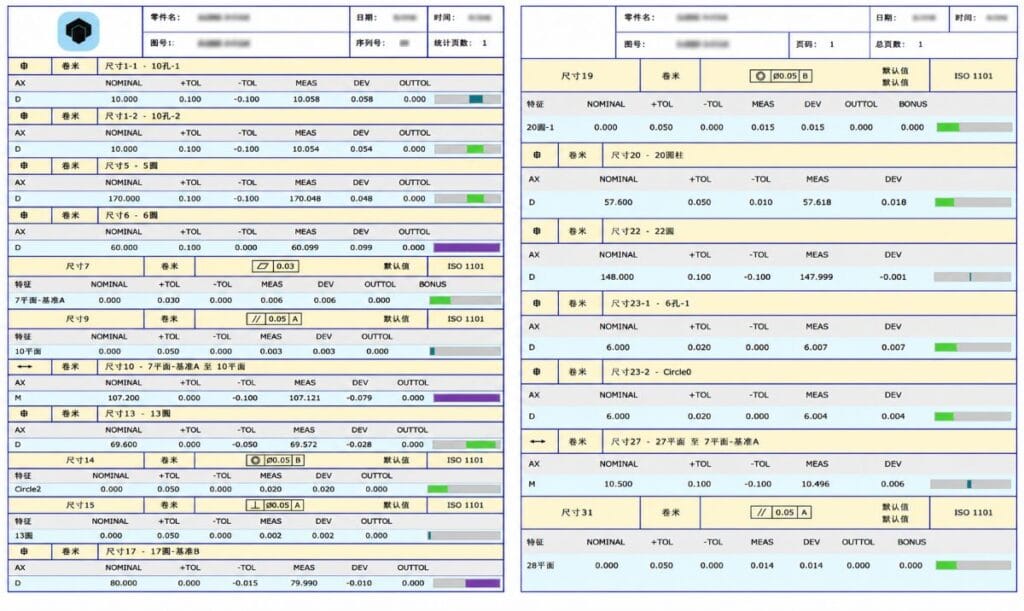
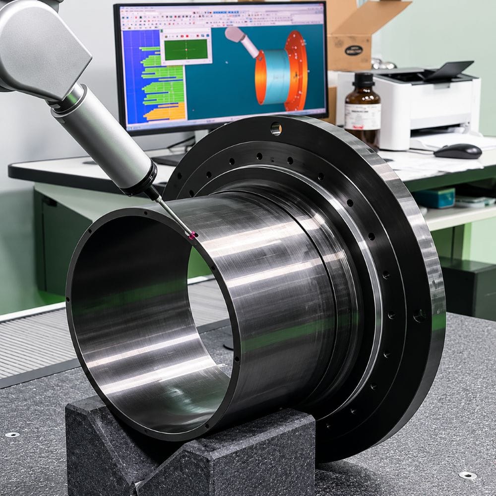
CMM inspection played a critical role in identifying dimensional movement that was not visible during machining.
After semi-finish machining, components were stabilized before entering final inspection. During verification, dimensional changes caused by residual stress release were identified and analyzed.
Inspection Findings
✓ Minor bore deformation
✓ Circularity variation
✓ Concentricity deviation
✓ Dimensional movement after machining
Without this inspection stage, these issues could have remained hidden until assembly, increasing the risk of rotor imbalance and performance variation.
Corrective Actions
✓ Additional stabilization period
✓ Inspection sequence optimization
✓ Datum verification
✓ Process compensation before final machining
These adjustments improved repeatability and prevented downstream assembly problems.
Why the 22°C Inspection Environment Matters
For thin-wall precision components, inspection conditions can be as important as machining accuracy.
All critical measurements were performed in a temperature-controlled inspection room maintained at approximately 22°C.
| Benefit | Impact |
|---|---|
| Temperature Stability | Reduces measurement variation caused by thermal expansion |
| Better Repeatability | Improves consistency between inspection cycles |
| Reliable GD&T Verification | Supports tight geometric tolerance evaluation |
Maintaining a stable inspection environment helped improve measurement reliability and reduced uncertainty across the entire production batch.
Project Results
| Item | Result |
|---|---|
| Material Certification | Passed |
| Heat Treatment Verification | Passed |
| Surface Finish Requirement | Ra 0.8 μm |
| Actual Surface Finish | Ra 0.29 μm |
| CMM Inspection | Passed |
| Batch Consistency | Verified |
The project demonstrated stable dimensional control from material preparation through final inspection, supporting consistent quality throughout batch production.
Key Takeaways
Material Selection
- Low-carbon steel provided stable magnetic performance.
- Better machinability helped maintain dimensional consistency.
- Suitable for batch production with controlled variation.
Heat Treatment Strategy
- Normalizing improved microstructural uniformity.
- Stress-relief annealing reduced residual machining stress.
- Lowered the risk of deformation in thin-wall sections.
Inspection Timing
- Dimensional changes did not appear immediately after machining.
- Stabilization in a controlled environment revealed hidden deviations.
- Early inspection prevented downstream quality issues.
Risk Prevention
- CMM scanning identified concentricity and circularity deviations.
- Process adjustments were completed before shipment.
- Potential assembly and performance problems were avoided.
Working on a Similar Component?
Whether you are developing a new rotor core design or evaluating an alternative manufacturing source, our engineering team can review your drawing and provide practical feedback on:
✓ Material Selection
✓ Heat Treatment Planning
✓ Machining Feasibility
✓ Inspection Requirements
Upload Your Drawing for Engineering Review
Receive practical manufacturing feedback on material selection, dimensional control, heat treatment planning, and inspection requirements before production begins.
Get Technical Feedback Within 24 Hours →