
Gear Assembly Components: Problems, Causes & Solutions
A gear shaft may pass dimensional inspection but still cause assembly problems when its gear teeth and bearing seats are not aligned to the required functional datums. Similar issues can affect other gear assembly components, including ring gears and transmission shafts.
In industrial transmission systems, runout, uneven tooth contact, backlash variation and bearing-fit problems can result from several interacting factors. For OEM engineers, understanding these problems helps identify which component features need tighter control and which manufacturing processes require closer review.
This guide examines common assembly-related problems, their possible causes and the forging, CNC machining and inspection measures used to manufacture custom gear components to OEM drawings.
Key Takeaways
- Gear shafts and ring gears may meet individual dimensional tolerances but still cause assembly problems if critical datum relationships are not properly controlled.
- Gear runout, uneven tooth contact and backlash variation may result from bearing-seat geometry, alignment errors or accumulated tolerances.
- Forging, heat treatment and precision CNC machining must be planned together to control dimensional changes, particularly in complex ring gears.
- OEM drawings should clearly specify functional datums, critical fits, geometric tolerances and inspection requirements to support reliable component manufacturing.
Why Can a Gear Shaft Pass Inspection but Cause Assembly Problems?
A gear shaft may pass inspection against its manufacturing datum but show excessive gear runout when checked relative to its bearing journals. One possible cause is a difference between the manufacturing, inspection and functional datums specified on the OEM drawing.
Manufacturing Datums vs. Functional Datums
A gear shaft may be machined between centers, with its gear teeth inspected relative to the center-hole axis. In service, however, the shaft rotates about an axis established by its bearing journals. If these axes differ beyond the specified limits, the gear runout measured from the functional axis may not match the earlier inspection result.
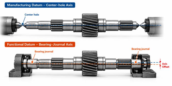
Gear shaft datum comparison: the center-hole axis used during machining and the bearing-journal axis used in service. Misalignment between these axes may affect gear runout.
The discrepancy does not necessarily originate in gear cutting. Bearing-journal machining, a later setup or an unsuitable inspection datum may be responsible. Engineers should compare the drawing requirements with the actual machining and inspection setups to identify where the error was introduced.
During CNC machining of custom gear shafts, setup sequences and reference surfaces should preserve the specified relationships between gear teeth, bearing journals and locating faces. Dial-indicator alignment can help reduce repositioning errors during a second setup, but final inspection must still verify the required dimensions and geometric tolerances against the drawing datums.
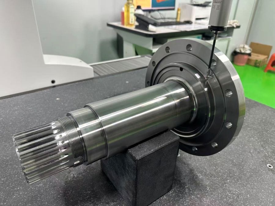
CMM inspection of a custom gear shaft. Critical dimensions and geometric tolerances are checked against the OEM drawing and inspection requirements.
What Causes Gear Misalignment and Uneven Tooth Contact?
Uneven tooth contact may appear as contact concentrated toward one end of the tooth face, sometimes accompanied by vibration, noise or localized wear.
The cause is not necessarily a gear-cutting error. Shaft deflection, bearing position, housing alignment, gear lead deviations and thermal movement can all affect the contact pattern. Before changing the manufacturing process, engineers need to determine whether the problem comes from component geometry, assembly alignment or operating conditions.
How Bearing Seats and Gear Geometry Affect Alignment
On a gear shaft, the relationship between bearing journals and gear geometry affects how the teeth align with the mating gear. For a ring gear, the mounting bore and locating faces can influence the position of the toothed section after installation.
When uneven contact is observed, the OEM should review the contact pattern and assembly alignment alongside component inspection results. This helps distinguish manufacturing deviations from housing or load-related effects.
For custom gear shafts and ring gears, manufacturing inspection should cover the specified bearing-seat geometry, locating surfaces, runout and relevant gear accuracy requirements. Controlling these features through gear machining and inspection helps reduce component-related alignment errors, although it cannot compensate for housing misalignment or excessive shaft deflection under load.
Why Can Gear Backlash Change After Assembly?
A gear pair may meet its individual tooth specifications yet show unexpected backlash after assembly. In some cases, the clearance also varies as the gears rotate.
Backlash depends on more than tooth thickness. Center distance, radial runout, bearing positions and the combined tolerances of mating components can all affect the result.
How Tolerance Stack-Up Affects Gear Mesh
Consider two gears installed on separate shafts. The tooth dimensions may be within specification, but variation in shaft locations, bearing fits and housing dimensions can change their effective center distance.
Radial runout may also contribute to backlash variation around the rotation.
Investigation should therefore include the specified tooth measurements, gear runout, center distance and relevant assembly dimensions.
For the component manufacturer, the practical requirement is to control the features identified on the OEM drawing and provide inspection results against the correct datums.
Backlash should not simply be reduced to the smallest possible value. The required range depends on the transmission design, operating temperature, lubrication and load conditions.
How Can Bearing-Seat Fits Lead to Gear Shaft Problems?
Bearing-seat problems may become visible through fretting marks, abnormal temperature rise or premature bearing damage. These symptoms do not identify a single cause, but the shaft fit is one area worth checking.
An unsuitable fit can permit unwanted movement between the bearing ring and its mounting surface. Excessive interference may also affect bearing internal clearance, depending on the bearing type and operating conditions.
Manufacturing accuracy matters beyond the nominal seat diameter. Roundness, cylindricity, surface finish and locating-shoulder geometry may also be specified.
Before changing the fit, engineers should check the bearing manufacturer’s recommendations, loading conditions and actual mounting arrangement.
For custom gear shafts, CNC finishing and dimensional inspection should verify the specified bearing-seat features. A first-part inspection can confirm the setup and measurement method before repeat production.
How Do Heat Treatment and Machining Cause Dimensional Changes?
Heat treatment can change component geometry through uneven heating and cooling, phase transformations and residual stress redistribution. Machining may cause further movement as material is removed and internal stresses are released. In thin-walled ring gears, these changes can affect roundness, runout and the relative position of mounting features. Clamping forces and limited rigidity may introduce additional distortion.
Comparing roundness, runout and critical locating features before and after key operations helps identify when dimensional changes occur. The results can guide adjustments to machining sequences, clamping methods and inspection plans.
Dimensional inspection alone does not verify the specified heat-treated condition. Where hardened case depth is required, representative test coupons can be used for verification. At Weforging, these coupons are identified and retained with the corresponding batch records, supporting material and heat-treatment traceability.
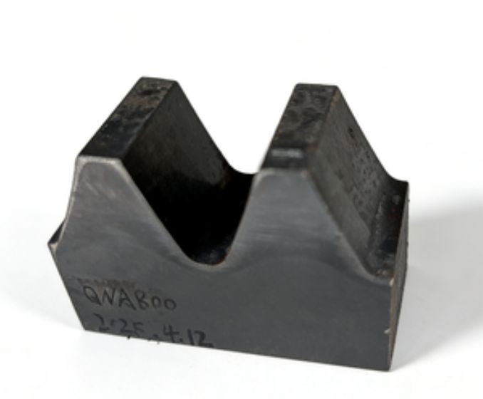
Manufacturing Constraints in Thin-Walled Internal Ring Gears
A custom internal ring gear used in a multi-stage speed-control actuator illustrates why machining feasibility should be reviewed before production.
Internal gear shaping requires sufficient clearance for the cutting tool and its operating motion. At the same time, the internal teeth must be machined in the specified relationship to the locating surfaces established in earlier operations.
Where the component includes two bearing locations, their relative geometry must also be considered during clamping and machining.
These requirements influence fixture design, cutting sequence and inspection planning. They cannot be addressed simply by selecting a more accurate machine tool.
For components manufactured from forged gear blanks, blank geometry, machining allowance and heat-treatment sequence should be reviewed together. Closed-die forging, ring rolling or other blank-production methods may be suitable depending on the part’s dimensions, material and quantity.
A forged blank does not eliminate distortion. The manufacturing plan must still provide a practical route to the final tolerances.
What Should OEMs Specify for Gear Assembly Components?
A component drawing should define the features critical to gear assembly performance, not just individual dimensions. Clear functional datums, fits and geometric tolerances help manufacturers plan machining and inspection around the intended application.
The table below links common assembly problems to information OEMs should include in their drawings or RFQs.
Observed Problem | Drawing or RFQ Requirements |
Excessive gear runout after mounting | Functional datums, bearing-journal references and specified runout tolerances |
Uneven tooth contact | Gear accuracy requirements, locating features and relevant mating-gear information |
Backlash variation | Tooth specifications, mating-gear data, critical component tolerances and assembly center distance where relevant |
Bearing-seat damage | Bearing-seat dimensions, fit and form tolerances, surface finish and bearing specifications |
Distortion after processing | Material, heat-treatment requirements, final geometric tolerances and agreed machining allowances where applicable |
For a manufacturing quotation, OEMs should also provide the drawing revision, order quantity, required delivery condition—forged blank, rough-machined part or finished component—and inspection documentation.
For complex gear shafts and ring gears, assembly drawings or mating-part information can help Weforging assess forging feasibility, CNC machining access and inspection requirements before production.
Custom Gear Components Manufactured to OEM Drawings
Weforging manufactures custom gear shafts, transmission shafts, ring gears and other gear components to OEM drawings, combining forging, heat treatment, CNC machining and inspection within the agreed production scope. Parts can be supplied as forged blanks, rough-machined parts or finished components.
For components with complex geometry or critical fits, assembly requirements and mating-part information help us assess forging feasibility, machining access and inspection needs before production. Send us your component drawings and relevant technical requirements for a manufacturing review and quotation.