
Robotic Parts: Tolerances, Machining & OEM Quality
By Weforging Technical Team | Updated October , 2026
Industrial robotic parts require more than accurate dimensions. Bearing interfaces, mounting faces and locating features must also meet the geometric tolerances defined in OEM drawings. Even when individual dimensions pass inspection, incorrect feature relationships can still cause assembly problems.
For OEM engineers and technical buyers, machining accuracy depends on clear drawing requirements, controlled setups and suitable inspection methods. This article explains which features require closer control, how machining setups affect geometric accuracy and what should be verified before custom robotic parts enter production.
Key Takeaways
- Critical tolerances should reflect each robotic part’s function, not apply equally to every feature.
- OEM drawings should clearly define functional datums, geometric tolerances and inspection requirements.
- Secondary machining setups require alignment checks to control critical geometric relationships.
- Inspection methods and acceptance criteria should be agreed upon before production begins.
- Approved samples, controlled drawing revisions and inspection records support consistent repeat OEM production.
Which Features Require Tight Tolerances in Robotic Parts?
Bearing bores, shaft journals, mounting faces and locating features often require tighter tolerances in precision robotic parts. Their requirements depend on how the component locates, supports or transmits loads within an assembly.
For example, bearing interfaces may require controlled fits, while locating holes and pilot diameters establish assembly positions. Rotating components may also need specific runout and alignment controls.
Internal ring gears used in robotic transmission systems provide another example. For these components, tooth geometry, mounting interfaces and runout must be controlled according to the gearbox design. Weforging’s forged internal ring gears illustrate how precision machining and inspection requirements extend beyond individual dimensions to functional gear engagement and alignment.
These requirements are particularly important for robot joint components, where critical features must maintain the geometric relationships defined in the OEM drawing. A bore can meet its diameter tolerance yet still fail the specified positional or orientation requirement relative to a functional datum.
Therefore, OEM engineers should prioritize tolerances according to assembly function rather than applying unnecessarily tight limits to every feature.
How Should OEM Drawings Define Machining Requirements?
OEM drawings for robotic parts should clearly define functional datums, critical dimensions, geometric dimensioning and tolerancing (GD&T) requirements, material specifications and inspection criteria.These specifications determine how a component is manufactured, measured and accepted.
Datum references are particularly important because they establish the geometric relationships used to evaluate critical features. If these references are unclear, the manufacturer and OEM may interpret or inspect the same requirement differently.
Before quotation and production, both parties should review the following requirements:
Drawing Requirement | Engineering Purpose | What OEMs Should Confirm |
Datum reference system | Establish geometric references | Datum features and reference relationships |
Dimensional tolerances | Control size and fit | Critical dimensions and tolerance limits |
Geometric tolerances | Control form, orientation, location and runout | Applicable GD&T and datum references |
Surface texture | Define functional surface requirements | Roughness parameters and measurement locations |
Material and heat treatment | Specify material condition and properties | Material grade, heat treatment and required properties |
Inspection requirements | Define acceptance evidence | Inspection methods, frequency and reporting format |
Confirming these details early helps manufacturers assess machining and inspection feasibility while reducing rework and acceptance disputes.
How Does Workpiece Setup Affect Robotic Parts Accuracy?
Secondary machining setups can affect runout, perpendicularity and other geometric relationships between critical features. When a workpiece is repositioned, even a small alignment error may affect the tolerances specified in the OEM drawing.
For custom robotic parts, Weforging’s CNC machining services include setup alignment checks where required by the machining plan. During secondary setups, machinists use dial indicators to check workpiece alignment and identify a suitable clamping position before machining continues.
This approach helps reduce setup-related variation and maintain the intended relationship between critical features. However, dial-indicator alignment is an in-process control, not a substitute for final inspection. Finished parts must still meet the applicable drawing requirements.
For details on forged blank design and process planning, see our guide to industrial robot components.
How Should Robotic Parts Be Inspected and Accepted?
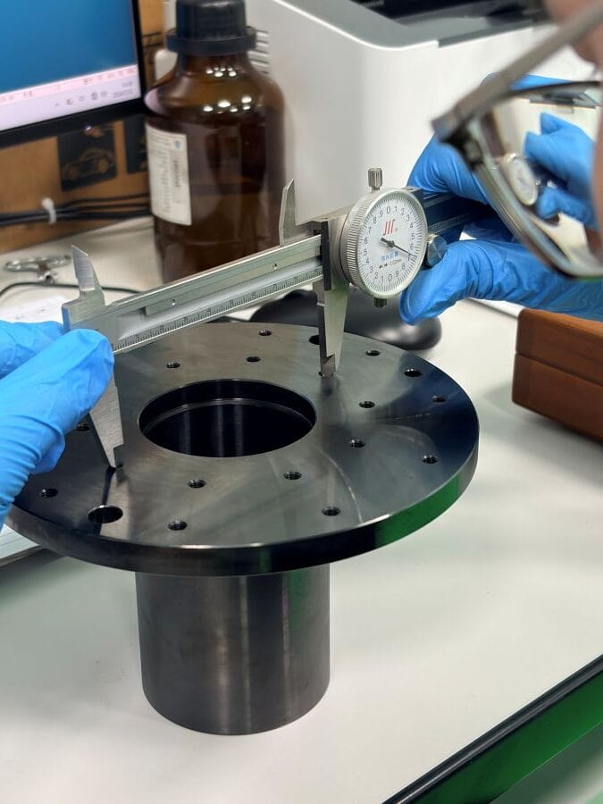
Robotic parts should be inspected against the OEM drawing using measurement methods suited to each critical feature. Acceptance depends on whether the measured results meet the specified dimensional and geometric tolerances under the agreed inspection criteria.
The inspection method must match the feature and tolerance being evaluated. For critical characteristics, datum references, measurement conditions and inspection frequency should be confirmed before production.
Critical Feature | Inspection Method | Acceptance Criteria |
Bearing bore diameter | Bore gauge or suitable dimensional equipment | Diameter within specified tolerance limits |
Feature position | CMM or suitable coordinate measurement | Position within the specified tolerance zone |
Runout | Dial indicator or suitable measuring system | Runout within the specified limit relative to the datum axis |
Mounting face flatness | Suitable flatness measurement method | Flatness within the specified tolerance |
Surface roughness | Surface roughness measuring instrument | Specified roughness parameter and acceptance limit |
At Weforging, quality control continues beyond CNC machining. Operators perform in-process checks, while inspection personnel independently verify finished parts. For critical features such as hole spacing and locating positions, dimensional measurements can be reviewed alongside CMM inspection data to confirm compliance with OEM drawing requirements.
These checks provide documented evidence that the inspected features meet the agreed OEM drawing requirements before the parts are accepted.
What Should OEM Buyers Verify Before Production?
Before production, OEM buyers should confirm the drawing revision, manufacturing feasibility, critical tolerances, sample approval requirements and inspection documentation for custom robotic parts. These details should be agreed upon by engineering, purchasing and the manufacturer before the order moves into production.
Supplier experience with similar components is valuable, but each drawing still requires a technical review. Complex datum relationships, difficult-to-machine features and production volume can affect the manufacturing plan, quotation and lead time. Requirements such as first-article inspection reports, material certificates and inspection frequency should also be confirmed in advance.
For load-bearing robotic components, the manufacturing review should also consider the appropriate forged blank. Depending on the geometry, material and production volume, custom forging or closed die forging may be suitable. For larger ring-shaped components, including certain gear blanks, rolled ring forging may offer an alternative. The final process should be selected according to the OEM drawing and functional requirements.
At Weforging, early technical review helps establish a suitable manufacturing route and confirm inspection expectations. Where required, approved samples can provide a reference for subsequent batch production.
How Are Quality Requirements Maintained Across Repeat Orders?
Consistent quality across repeat OEM orders depends on controlled drawing revisions, approved machining requirements and defined inspection criteria. An approved sample provides a reference, but it does not replace process control during subsequent production.
When an OEM drawing changes, the manufacturer should review any affected datums, tolerances and mating features. These changes may require adjustments to machining setups, inspection methods or sample approval before the next batch begins.
At Weforging, approved samples and inspection records support repeat production. Where required, production batches are linked to material, heat treatment and inspection records through traceability documentation and part identification.
As a result, each repeat order can be manufactured and inspected against the applicable approved requirements rather than relying solely on previous production results.
Conclusion
Reliable robotic parts manufacturing depends on clear OEM drawings, controlled machining processes and inspection against defined acceptance criteria. For OEM buyers, these controls help reduce assembly risks and support consistent quality across repeat production orders.
At Weforging, we manufacture custom metal robotic parts to customer drawings, coordinating manufacturing and inspection to meet project-specific requirements.
Send us your drawing to discuss manufacturing feasibility, critical tolerances and your OEM production needs.