
Industrial Robot Components: From Forged Blanks to CNC Machining
By Weforging Technical Team | Updated October 2026
Industrial robot components such as joint shafts, hubs and flanges may require forged blanks and precision CNC machining to meet mechanical and dimensional requirements. However, the manufacturing route depends on each component’s geometry, material and operating conditions.
For forged components, machining allowances, locating surfaces and process sequence directly influence final accuracy. Poor coordination between forging, heat treatment and CNC machining can also increase the risk of dimensional variation.
Therefore, OEM engineers should evaluate blank design, machining stability and critical-feature inspection before series production. These decisions help establish a controlled manufacturing process for repeat orders.
Key Takeaways
- Forging suitability:Component geometry, loading and production volume determine whether forging is appropriate.
- Blank design:Machining allowances and locating surfaces affect machining accuracy and setup stability.
- Process planning:Heat treatment and machining sequence should account for critical bearing and mounting features.
- Dimensional stability:Residual stress and material removal can cause geometric changes after machining.
- OEM validation:Engineers should verify critical tolerances and manufacturing conditions before series production.
When Should Industrial Robot Components Use Forged Blanks?
Forged blanks are suitable for industrial robot components when loading requirements, part geometry and production volume justify forging. Joint shafts, hubs and load-bearing flanges may benefit from forging when the process can meet the specified mechanical properties and reduce material waste.
For components with suitable geometry and repeat production volumes, closed die forging can produce near-net-shape blanks that reduce the amount of material removed during subsequent CNC machining.
However, not every robot component requires forging. OEM engineers should compare the manufacturing options based on the drawing, material requirements and total production cost.
Manufacturing Factor | What OEM Engineers Should Evaluate |
Loading and material properties | Assess strength, fatigue requirements and material specifications |
Component geometry | Determine whether forging offers a suitable near-net shape |
Production volume | Compare tooling investment with expected order quantities |
Total manufacturing cost | Evaluate material use, forging costs and subsequent CNC machining |
For example, forging may be appropriate for a load-bearing robot joint shaft produced in repeat batches. By contrast, a simple component ordered in small quantities may be more economical to machine.
For a broader overview of component types and manufacturing options, see our guide to robot parts.
How Forged Blank Design Affects Precision Machining
Forged blank design affects machining accuracy through stock allowance, material distribution and locating surfaces. Therefore, engineers must consider CNC machining requirements before finalizing the blank geometry. Poor blank design can increase machining time and make critical dimensions harder to control.
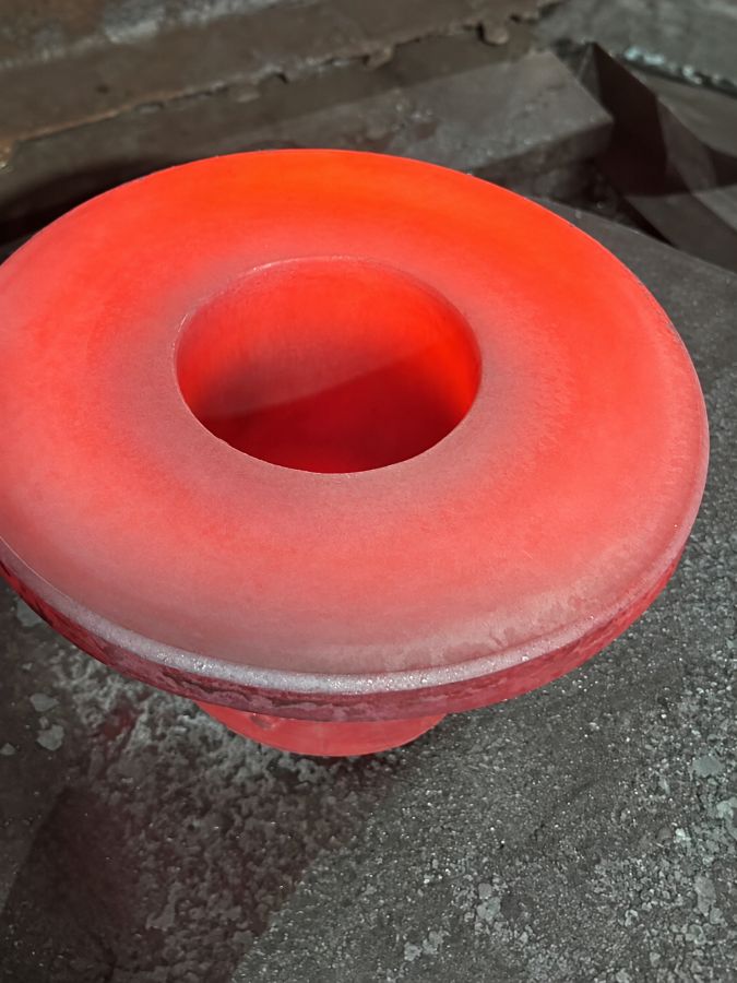
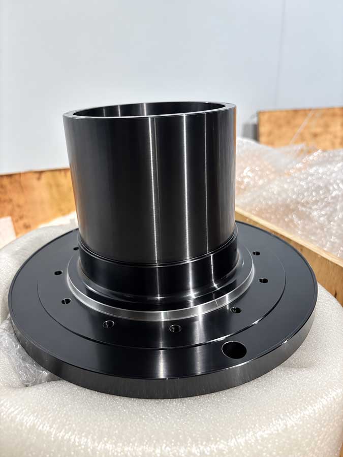
The photos below show a robot joint rotor core at two manufacturing stages: a hot-forged blank and the finished CNC-machined component. The comparison illustrates how forging establishes the initial geometry, while precision machining produces the required bores, mounting surfaces and other functional features.
Machining Stock and Material Distribution
Machining allowances should account for forging tolerances, surface conditions and the finished drawing. Insufficient stock may prevent complete machining of critical surfaces. Conversely, excessive or uneven stock increases material removal and may contribute to distortion.
For bearing seats, mounting faces and precision bores, engineers should define sufficient and reasonably balanced machining allowances.
Locating Surfaces and Machining Datums
Stable locating surfaces help control part positioning during CNC machining. However, machining datums must also align with the functional requirements defined on the drawing.
For example, a bearing seat may meet its diameter tolerance but still fail assembly if its position relative to a mounting datum is incorrect.
During custom forging, engineers should consider how the blank will be located and machined to meet these requirements.
Planning CNC Machining Around Heat Treatment and Critical Features
The machining sequence for industrial robot components should account for heat treatment, material condition and critical tolerances. In particular, engineers must identify which operations could affect the geometry of bearing seats, precision bores and mounting surfaces.
Heat treatment can change material properties and dimensions. Therefore, its timing should be considered alongside rough machining and final finishing. Rough machining removes the planned stock while retaining sufficient allowance for critical features.
For precision components, manufacturers may finish bearing seats and mounting surfaces after operations that could affect their geometry. Thin-walled parts may also require intermediate stress-relief treatment, depending on the material and process validation results.
By coordinating heat treatment with CNC machining services, manufacturers can better control material condition, final tolerances and inspection requirements throughout production.
Why Dimensional Accuracy Can Change After Machining
Precision-machined robot components can experience dimensional or geometric changes during machining, after unclamping or during subsequent handling. Residual stress redistribution, uneven material removal and clamping forces are common contributing factors.
Thin-walled components are especially sensitive because their lower stiffness increases the risk of deformation. For example, a precision bore may meet its diameter requirement while still showing roundness or form errors after the part is released from its fixture.
To control these risks, engineers may adjust the machining sequence, clamping method or material removal strategy. Stress-relief treatment or a defined stabilization period may also be appropriate when supported by process validation. The corrective action should address the identified cause rather than rely on additional machining alone.
Engineering Example: Dimensional Changes in a Robot Rotor Bore
In a Weforging robot joint rotor project, thin-wall geometry made bore accuracy and dimensional stability important manufacturing considerations. Controlling the bore required attention not only to diameter but also to its geometric form and relationship with other functional surfaces.
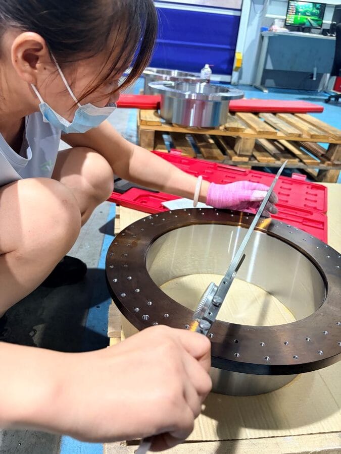
In this robot joint rotor project, bore inspection formed part of the dimensional verification process. The inspection photo shows a technician checking the machined bore with a measuring instrument. However, diameter checks alone do not establish compliance with all applicable geometric tolerances.
This example illustrates why a single diameter measurement cannot fully establish bore conformity. Inspection must follow the drawing’s applicable dimensional and geometric tolerances.
Further manufacturing details are available on our Robot Joint Components page.
Verifying Critical Features Before Series Production
Before series production, industrial robot components should be verified against the drawing’s critical dimensions, geometric tolerances and material requirements. Inspection should focus on features that affect assembly and operation, rather than dimensional measurements alone.
Inspection Area | Verification Requirement |
Bearing seats | Diameter, applicable form tolerances and fit requirements |
Rotating interfaces | Runout and geometric tolerances specified on the drawing |
Mounting faces | Flatness, position and relationships to assembly datums |
Material condition | Required mechanical properties and heat treatment results |
First finished part | Critical dimensions and agreed acceptance criteria |
For complex components, CMM inspection can verify selected geometric relationships between functional features. However, measurement methods must match the drawing requirements and applicable tolerances.
At Weforging, operators check dimensions during first-part machining. Once the first finished component is completed, quality inspectors perform an independent inspection. Where required, laboratory testing verifies material properties and heat treatment results.
These checks provide documented evidence of conformity before the manufacturing process proceeds to series production.
Manufacturing Process Approval for OEM Production
A conforming sample alone does not demonstrate a stable manufacturing process. Before approving series production, OEM engineers should confirm that the selected manufacturing route can consistently meet drawing requirements across production batches.
Process approval should cover forged blank specifications, heat treatment requirements, machining sequence, critical tolerances and agreed inspection methods. Changes to materials, tooling or manufacturing operations should also be reviewed and controlled according to project requirements.
For long-term OEM programs, traceability should link material heat numbers, production batches, heat treatment records and inspection results. Where specified, part marking can support identification and batch tracking.
An integrated machined forgings supplier can reduce coordination between separate forging and machining providers. More importantly, the approved manufacturing conditions must be maintained so that subsequent orders can be produced and verified against the same requirements.
Conclusion
For forged industrial robot components, dimensional accuracy depends on coordinated blank design, heat treatment where required, and precision CNC machining. Identifying potential distortion risks and verifying critical features before series production helps establish a controlled process for consistent OEM manufacturing.
For custom joint shafts, hubs, flanges and other robotic components, explore Weforging’s Robot Joint Components capabilities. Send us your drawings, material requirements and expected production quantities for a manufacturing review and quotation.